 English
 Russian
 German
 French
 Italian
 Spanish
 Partuguese
 Greek
Greek Japanese
 Korean
 Turkish
 Polish
 Arabic
Complete Guide to FTTH ODN: Architecture, Components and Network Design
An FTTH ODN (Optical Distribution Network) is the all-passive optical path between the OLT in the central office and the ONT at each subscriber premises. It spans the feeder, distribution and drop segments together with the splitters, closures, terminals and cabinets that join them — and contains no powered electronics at any point between the two ends.
That paragraph is the whole idea. Everything else in this guide is the detail behind it: how the chain is built, what each box is actually called, how splitter ratios consume your optical budget, and which component decisions determine whether a build passes acceptance testing the first time.
It is written for network planners, ISP engineers, contractors and procurement teams who have to specify an ODN rather than read about one. Sections follow the signal path in order — from the OLT port to the customer socket.
Contents
- 1. What Is an FTTH ODN?
- 2. The ODN Architecture: From OLT to ONT
- 3. FTTH ODN Terminology Decoded
- 4. PON Splitters: Types, Ratios and Loss
- 5. Closures, Terminals, Cabinets and Frames
- 6. Drop Cable and the Last Mile
- 7. ODN Loss Budget and Reach Design
- 8. Installation, Splicing and Testing
- 9. How to Choose an FTTH ODN Supplier
- 10. Frequently Asked Questions
1. What Is an FTTH ODN?
The optical distribution network is defined in the ITU-T G.984.1 recommendation as the passive optical infrastructure connecting the optical line terminal to the optical network units. In plain terms, it is everything optical that sits between the operator’s equipment and the customer’s equipment — and it is the part of an FTTH network that has no power supply anywhere in it.
FTTH access networks are built as a point-to-multipoint topology. A single OLT port transmits downstream on 1490 nm and receives upstream on 1310 nm, and that one port serves dozens of subscribers simultaneously through passive optical splitters. The splitter does not switch or route; it divides optical power. Every subscriber receives the same downstream transmission and reads only the time slots addressed to them, while upstream traffic is scheduled in assigned time slots so that no two ONTs transmit at once.
This is why the ODN is described as passive, and why that word carries commercial weight:
- No field power. No remote nodes, no batteries, no UPS, no electricity at the cabinet. The ODN survives a local power outage because there is nothing in it to fail.
- No electronics to upgrade. Capacity changes are made at the OLT optics, not by replacing street furniture.
- Design life measured in decades. Passive optical components do not become obsolete at the pace of transceiver generations, so the outside plant built for GPON today is normally reused for XGS-PON later.
- Lowest operating cost in the network. Once installed, the ODN consumes no energy and requires only occasional cleaning, re-splicing and fault repair.
The ODN is also the largest single capital cost block in most FTTH builds. Civil works, cable, closures, terminals and the labour to install them typically outweigh the cost of the active equipment at both ends — which is the practical reason a guide like this exists. Decisions made in the ODN are expensive to reverse, and there is no software upgrade that compensates for a split ratio chosen badly.
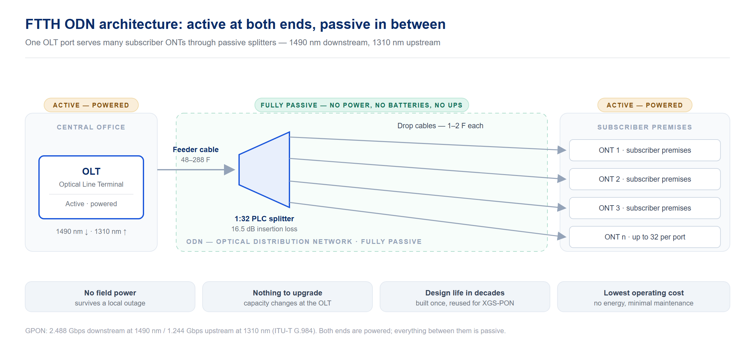
Quick answer: ODN stands for Optical Distribution Network. It is the passive fiber path — splitters, closures, terminals, cabinets and cable — between the OLT and the subscriber’s ONT. It carries no electrical power and no active electronics.
2. The ODN Architecture: From OLT to ONT
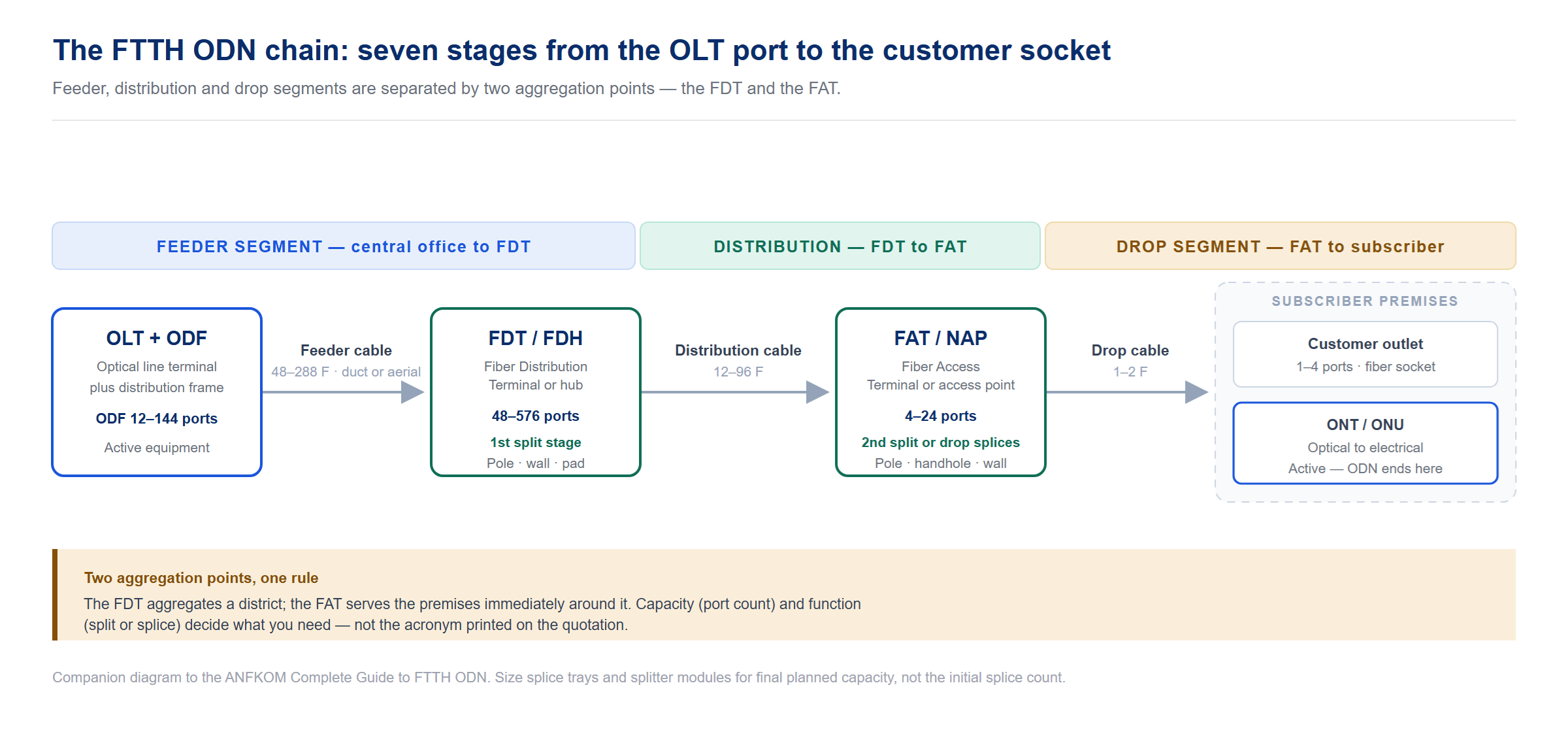
A conventional FTTH ODN is organised into three cable segments — feeder, distribution and drop — separated by two aggregation points. Understanding which point does what is the difference between a design that can be commissioned and one that gets re-spliced on site.
Feeder segment: OLT to FDT
The feeder runs from the central office to the fiber distribution terminal serving a catchment area. It carries the highest fiber count in the ODN — commonly 48 to 288 fibers — and is normally installed in duct or as aerial cable with a substantial strength member. At the central office end, the feeder is terminated on an optical distribution frame, which is the cross-connect point between OLT ports and outside-plant fibers.
The first splitter stage often sits at the central office or the FDT. Placing the first splitter centrally, rather than at the FDT, reduces the number of feeder fibers required and concentrates the splitter in a controlled environment — at the cost of a higher loss floor for every subscriber on that port.
The FDT: Fiber Distribution Terminal
The FDT — also called FDH (fiber distribution hub) or, in some markets, an FDB — is the cabinet that aggregates a neighbourhood. It is where a high-count feeder is split or cross-connected into several lower-count distribution cables. FDT cabinets typically house 48 to 576 termination ports with splice trays and splitter modules, and are pole-mounted, wall-mounted or pad-mounted depending on the environment.
Distribution segment: FDT to FAT
Distribution cables leave the FDT and run to each FAT. Fiber counts are usually 12 to 96, sized to the number of premises the FAT will serve plus provision for growth. Where aerial construction is used, the distribution cable is often lashed to the same pole line that carries the drop spans, so the FAT can be placed immediately where the drops branch off.
The FAT: Fiber Access Terminal
The FAT — known in different markets as a network access point, access terminal box or fiber distribution box — is the last aggregation point before the customer. It holds the second splitter stage or a straight splice to individual drop cables, and presents 4, 8, 16 or 24 ports depending on the served premises. Because it sits outdoors on a pole, in a handhole or on a wall, its environmental rating matters more than its port count.
Drop segment and the customer premises
Drop cables leave the FAT and reach each subscriber, and are covered in detail in section 6. At the premises, the drop is terminated on an outlet — a fiber socket, wall box or rosette — which provides the transition from the incoming outdoor cable to the indoor patch cord that connects to the ONT. The ONT performs the optical-to-electrical conversion and hands off to the customer’s router.
| Stage | Where it sits | Typical fiber / port count | Passive component |
|---|---|---|---|
| OLT + ODF | Central office | ODF: 12–144 ports per frame unit | Optical distribution frame, patch panel |
| Feeder cable | CO → FDT | 48–288 F, duct or aerial | — |
| FDT / FDH | Neighbourhood, pole / wall / pad | 48–576 ports | Distribution cabinet, splitter modules, splice trays |
| Distribution cable | FDT → each FAT | 12–96 F | — |
| FAT / NAP | Pole, handhole, wall | 4–24 ports | Access terminal box, splitter or splice |
| Drop cable | FAT → premises | 1–2 F | — |
| Customer outlet | Inside premises | 1–4 ports | Fiber socket, wall box, rosette |
| ONT / ONU | Customer premises | 1–4 subscriber ports | Active equipment (end of the ODN) |
Recommended products for this stage
- FDT / distribution cabinets — Fiber Distribution Terminal Cabinet FDT(06) and the wider distribution cabinet range
- Access terminals — 24-core Fiber Access Terminal FAT-24C and FAT-16F
- Central office termination — ODF patch panel with door, part of our full patch panel and ODF range
3. FTTH ODN Terminology Decoded
One of the most common sources of error in ODN procurement is that the same box is sold under several different names, and different boxes are occasionally sold under the same name. The terms below are the ones that appear in tender documents and vendor catalogues.
| Term | Stands for | What it does in the ODN |
|---|---|---|
| ODN | Optical Distribution Network | The complete passive path between OLT and ONT |
| PON | Passive Optical Network | The point-to-multipoint access architecture the ODN serves |
| OLT | Optical Line Terminal | Operator-side equipment that terminates the PON and manages all ONUs |
| ONT / ONU | Optical Network Terminal / Unit | Customer-side unit; converts optical to electrical at the premises |
| ODF | Optical Distribution Frame | Rack-mounted cross-connect between OLT ports and outside-plant fiber |
| FDT | Fiber Distribution Terminal | Neighbourhood cabinet; first split or cross-connect point |
| FDH | Fiber Distribution Hub | Same function as FDT; the term is more common in North America |
| FDB | Fiber Distribution Box | Usually a smaller wall- or pole-mounted distribution enclosure |
| FAT | Fiber Access Terminal | Last aggregation point; holds the second splitter or drop splices |
| NAP | Network Access Point | Same function as FAT; common terminology in European tenders |
| ATB | Access Terminal Box | Small terminal box for one or a few subscribers |
| OTB | Optical Terminal Box | Generic name for a termination enclosure; capacity varies widely |
| FIC | Field Installable Connector | Connector assembled on site without fusion splicing |
| SDU / MDU | Single / Multiple Dwelling Unit | Describes the customer premises type; drives drop architecture |
| GPON | Gigabit-capable PON | ITU-T G.984; 2.488 Gbps down, 1.244 Gbps up |
| XGS-PON | 10-Gigabit-capable symmetric PON | ITU-T G.9807.1; 10 Gbps symmetric, often overlaid on GPON |
| EPON | Ethernet PON | IEEE 802.3ah; 1.25 Gbps symmetric |
The naming trap to watch for: FDT, FDH and FDB are used interchangeably by different suppliers, as are FAT, NAP and ATB. Capacity and function, not the acronym, determine what you actually need. When comparing quotations, normalise every line item to three attributes — port count, splitter or splice function, and environmental rating — before comparing price.
4. PON Splitters: Types, Ratios and Loss
Optical splitters are the components that convert one OLT port into many subscriber ports, and they are the single largest loss contributor in any ODN. Choosing between splitter technologies and ratios is therefore the central engineering decision of the whole design.
PLC versus FBT splitters
Two technologies dominate. Planar lightwave circuit splitters are manufactured by etching waveguides onto a silica substrate; fused biconical taper splitters are made by fusing and tapering two or more fibers together.
| Property | PLC (Planar Lightwave Circuit) | FBT (Fused Biconical Taper) |
|---|---|---|
| Available ratios | 1×2 to 1×128, and 2×N | Typically 1×2 to 1×8 |
| Wavelength range | 1260–1650 nm, wideband | Narrower; performance varies by wavelength |
| Uniformity across ports | Good; excellent at higher counts | Degrades quickly beyond 1×4 |
| Split ratio accuracy | High; supports unequal ratios precisely | Good for 50/50 and simple ratios |
| Best suited to | PON networks, higher ratios, wideband use | Low ratios, CATV, simple low-cost splitting |
For PON deployment, PLC is the default choice from 1:8 upward. FBT remains sensible where only a 1:2 or 1:4 split is required and cost is the governing factor.
Splitter loss by ratio
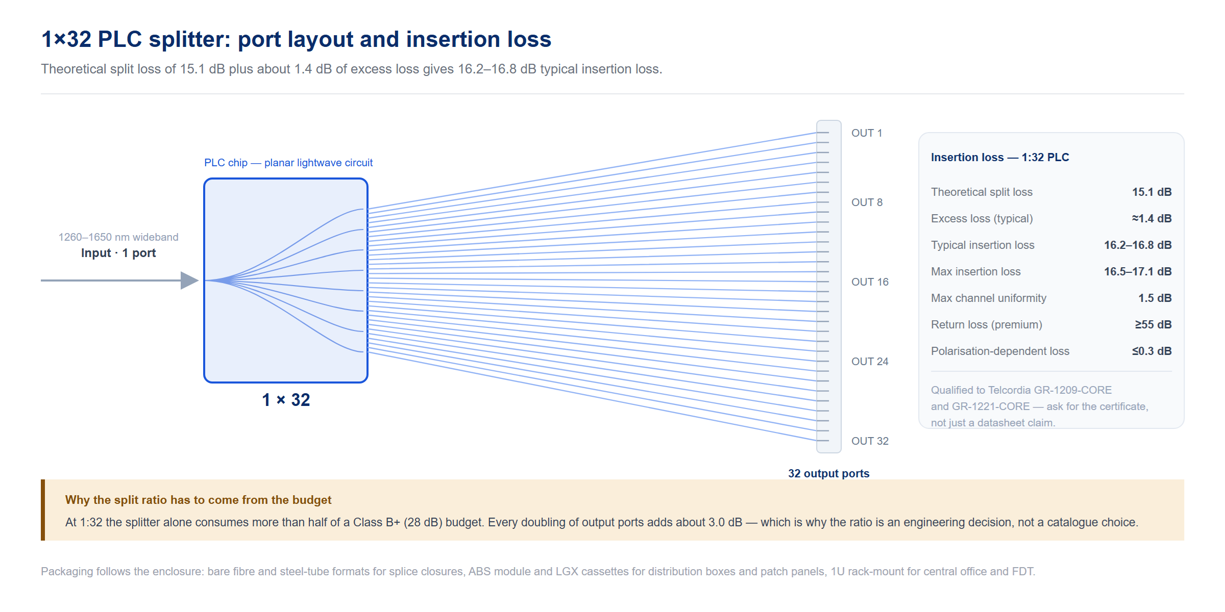
Every doubling of output ports adds roughly 3.0 dB of theoretical splitting loss, before the excess loss introduced by the device itself. The table below combines the theoretical figure with typical and maximum insertion loss values, and the maximum channel uniformity you should hold a supplier to.
| Ratio | Theoretical split loss | Typical insertion loss | Max insertion loss | Max uniformity | Practical note |
|---|---|---|---|---|---|
| 1:2 | 3.0 dB | 3.5–3.6 dB | 3.8–4.0 dB | 0.4 dB | Used at the OLT or as first stage |
| 1:4 | 6.0 dB | 6.8–7.0 dB | 7.2–7.4 dB | 0.6 dB | Common first stage of a cascade |
| 1:8 | 9.0 dB | 10.0–10.2 dB | 10.5–10.7 dB | 0.8 dB | Upper limit for FBT equivalents |
| 1:16 | 12.0 dB | 13.1–13.5 dB | 13.5–13.7 dB | 1.2 dB | Typical second stage in MDU designs |
| 1:32 | 15.1 dB | 16.2–16.8 dB | 16.5–17.1 dB | 1.5 dB | Comfortable within a Class B+ budget |
| 1:64 | 18.1 dB | 20.0–20.5 dB | 20.5–21.2 dB | 2.0 dB | Needs Class C+ once feeder length is real |
| 1:128 | 21.1 dB | 23.8–24.0 dB | 24.2–24.8 dB | 2.5 dB | Only with high-budget optics and short drops |
Values are representative for single-mode, equal-split, connectorised PLC devices operating across 1260–1650 nm. Return loss is typically ≥55 dB premium / ≥50 dB standard, directivity ≥55 dB, and polarisation-dependent loss ≤0.2 dB at low counts rising to ≤0.4 dB at 1:64 and above. Quality splitters are qualified to Telcordia GR-1209-CORE and GR-1221-CORE; ask for that qualification rather than accepting a datasheet claim.
Cascaded splitters
Total split ratio can be reached in stages — for example 1:4 at the FDT followed by 1:16 at the FAT, giving 1:64 overall. Cascading adds flexibility and reduces the number of feeder fibers, but it is not free: you pay the sum of both splitters’ insertion loss (about 24 dB rather than the 20.5 dB of a single 1:64), plus the additional connector and splice losses at the intermediate point. Always budget the cascade as a whole link, not as two independent stages.
Splitter packaging follows the enclosure it has to live in. Bare and steel-tube splitters are used inside splice closures and trays; ABS module and LGX cassette formats slot into distribution boxes and patch panels; 1U rack-mount units suit central office and FDT installations where a large ratio has to be presented on standard adapters.
Recommended products for this stage
- High-ratio PLC — Cassette 1×64 PLC splitter and the full fiber optic splitter range
- Rack-mount PLC — 1U rack-mount PLC splitter and 2×32 rack-mount splitter
- Low-ratio FBT — 1×2 FBT coupler, 50/50 to 99/1
5. Closures, Terminals, Cabinets and Frames
The passive enclosures are what turn loose cable into a maintainable network. They are frequently specified badly, because the four families look similar in a catalogue photograph but do completely different jobs.
| Family | Function | Typical capacity | Where it goes |
|---|---|---|---|
| Splice closure (inline or dome) | Protects fusion splices and stores slack; no user ports | 12–288 splices | Duct, handhole, buried, aerial span joints |
| Access terminal / FAT | Terminates distribution fiber and presents drop ports; splits or splices | 4–24 ports | Pole, wall, handhole at the drop point |
| Distribution cabinet / FDT | Cross-connects feeder to distribution; houses first splitter stage | 48–576 ports | Street cabinet, pad-mounted or pole-mounted |
| ODF / patch panel | Rack cross-connect between OLT ports and outside plant | 12–144 ports per unit | Central office, equipment room |
| Customer outlet | Terminates the drop and presents an indoor socket | 1–4 ports | Inside the premises |
Inline versus dome closures
Inline closures are used where a cable continues past the joint — the closure sits in the cable run and carries splices for through-traffic. Dome closures are used at cable ends, branching points and where a splitter has to be housed in the field. Both are available for buried, duct and aerial installation, and the choice is usually driven by whether the cable terminates there or passes through.
Environmental ratings that actually matter
Rating decides service life far more than wall thickness does. For direct-buried and handhole installation, IP68 is the working specification. For pole- and wall-mounted enclosures above ground, IP55 to IP65 is normally sufficient, but UV stability of the housing material is equally important — an enclosure that survives water ingress and then embrittles in sunlight has not solved the problem. For aerial drop hardware, add resistance to wind-induced vibration and, where rodents are a known issue, consider anti-rodent cable construction upstream.
Inside the enclosure, splice trays and splitter modules determine how maintainable it will be. A closure specified at the right capacity but with insufficient tray count will be re-entered within a year; specify trays for the final planned capacity, not just the initial splice count.
Recommended products for this stage
- Splice closures — AFC-M12AX inline closure, AFC-M dome closure, or the full splice closure range
- Terminal boxes — 16-port FAT-16H OTB within our 80-model termination box range
- Customer outlets — AFS-2D customer terminal box and AFC-2C 2-core rosette from the fiber optic outlet range
6. Drop Cable and the Last Mile
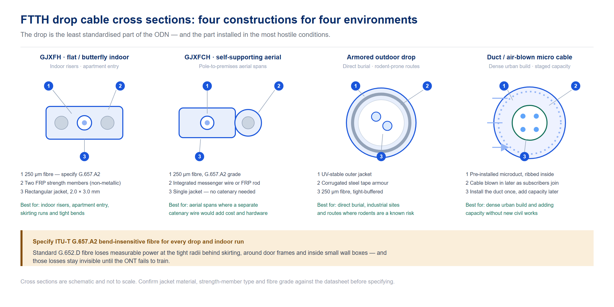
The drop is the least standardized part of the ODN and the one most often underestimated. It is installed in the most hostile conditions — cable trays, façade runs, aerial spans, duct entries — and it is where bend losses and installation damage actually appear.
Construction types
| Type | Construction | Best used for | Notes |
|---|---|---|---|
| Flat / butterfly indoor (e.g. GJXFH) | Two parallel strength members flanking a 250 µm fiber; rectangular jacket | Indoor risers, apartment entry, skirting runs | Non-metallic strength members; stapling and tight bends are tolerated |
| Self-supporting aerial (e.g. GJXFCH) | Drop cable with an integrated messenger wire or FRP rod | Aerial spans from pole to premises | Eliminates a separate catenary wire; span length limited by ice and wind loading |
| Armored outdoor drop | Steel tape or corrugated armor under the jacket | Direct-burial, rodent-prone, industrial sites | Higher cost and stiffness; needs careful bend-radius planning |
| Duct / air-blown micro cable | Small-diameter cable installed by air pressure into pre-laid microduct | Dense urban build, later capacity addition | Install the duct once and blow cable as subscribers connect |
For indoor and drop applications, specify bend-insensitive fiber — ITU-T G.657.A2 or better. Standard G.652.D fiber suffers measurable loss at the tight radii that occur behind skirting, around door frames and inside small wall boxes, and those losses are invisible until the ONT fails to train. G.657 is the single most valuable specification decision on the drop.
Connecting the drop: fusion, mechanical splice or field-installable connector
| Method | Typical loss | Advantages | Limitations |
|---|---|---|---|
| Fusion splice | ≤0.1 dB (average ~0.05 dB) | Lowest loss, most reliable, permanent | Requires a fusion splicer and trained technician |
| Mechanical splice | ≤0.3–0.5 dB | No splicer needed; fast; good for restoration | Higher loss; index-matching gel can degrade over time |
| Field-installable connector (FIC) | ≤0.3–0.5 dB | No splicer; allows plug-in connection at the FAT or outlet | Depends heavily on operator skill and cleave quality |
In practice most operators fuse in the FAT and at the customer end, and reserve fast connectors for restoration, temporary service and situations where carrying a splicer to the last subscriber is uneconomic. Whichever method is used, cleaning before mating is not optional — a single contaminated connector endface can add several dB of loss and is one of the most common causes of a failed acceptance test.
Recommended products for this stage
- Drop cable — GJXFCH self-supporting aerial drop cable, GJXFH butterfly flat indoor drop cable, single-armored outdoor drop cable — see the full FTTH cable range
- Field-installable connectors — SC fast connector for 0.9/2.0/3.0 mm cable, quick assembly connector, and our FIC connector range
- Pigtails for fusion — 12-colour pigtail set from the FTTH pigtail range
7. ODN Loss Budget and Reach Design
The loss budget is the difference between the OLT’s launch power and the receiver sensitivity of the ONT. It is the envelope that the entire ODN has to fit inside, and it is fixed by the optical class of the transceivers rather than by the outside plant.
For GPON, ITU-T G.984.2 defines the classes. Class B+ provides approximately 28 dB of budget with a typical split ratio of 1:32 and a reach of about 20 km. Class C+ extends this to approximately 32 dB, which is what makes a 1:64 split practical once real feeder length accumulates. The 10-gigabit generations use different class names — N1, N2, E1 and E2 for XG-PON and XGS-PON — with budgets running from roughly 29 dB to 35 dB.
What consumes the budget
- Splitter insertion loss — the dominant item, from 3.6 dB at 1:2 to more than 20 dB at 1:64
- Fusion splices — budget 0.1 dB each; a 1:32 design with 15 splices consumes 1.5 dB
- Connector pairs — budget 0.3–0.5 dB per mated pair; ODF, FDT, FAT and ONT each contribute
- Fiber attenuation — approximately 0.35 dB/km at 1310 nm and 0.2–0.25 dB/km at 1490/1550 nm for standard single-mode fiber
- Coexistence filters — where GPON and XGS-PON share one ODN, add 0.5–1.0 dB
- Design margin — allow 3 dB for ageing, temperature variation and future re-splicing
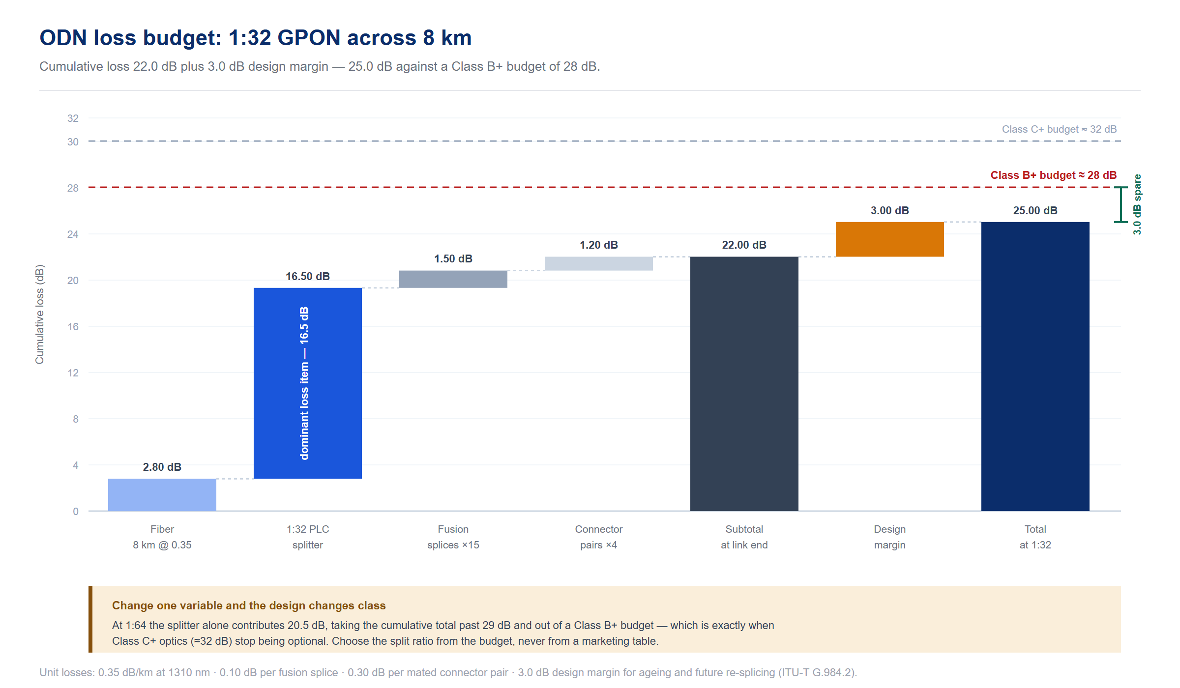
Worked example: 1:32 GPON across 8 km
| Item | Quantity | Unit loss | Total |
|---|---|---|---|
| Fiber (feeder + distribution + drop) | 8 km | 0.35 dB/km @ 1310 nm | 2.80 dB |
| 1:32 PLC splitter | 1 | 16.5 dB max | 16.50 dB |
| Fusion splices | 15 | 0.10 dB | 1.50 dB |
| Connector pairs | 4 | 0.30 dB | 1.20 dB |
| Subtotal | 22.00 dB | ||
| Design margin | 3.00 dB | ||
| Total against Class B+ (28 dB) | 25.00 dB — passes with 3.0 dB spare |
Change one variable and the design changes class. Move to a 1:64 split and the splitter alone contributes 20.5 dB, taking the total past 29 dB and out of a Class B+ budget — which is exactly the point at which Class C+ optics become mandatory rather than optional. This is why the split ratio should be chosen from the budget, never from a marketing table.
Split ratio against reach
| Split ratio | Splitter loss | Approximate reach on Class B+ (28 dB) | Approximate reach on Class C+ (32 dB) |
|---|---|---|---|
| 1:16 | 13.5 dB | ~30 km | ~40 km |
| 1:32 | 16.5 dB | ~20 km | ~30 km |
| 1:64 | 20.5 dB | ~12 km | ~20 km |
| 1:128 | 24.0 dB | Not practical | ~12 km with margin |
Reach figures are indicative once typical splice and connector losses are included, and assume a 3 dB margin. Also note the lower bound: each optical class specifies a maximum input power at the receiver, so a link that measures far cleaner than expected can overload the ONT just as a lossy link underruns it. Very short links with low split ratios are worth checking against the overload specification.
8. Installation, Splicing and Testing
An ODN that is designed correctly and installed carelessly will still fail. The three disciplines that decide the outcome are splicing quality, endface cleanliness and test coverage.
Splicing and termination
Fusion splicing remains the reference method for permanent joints, with typical losses at or below 0.1 dB and the least sensitivity to the environment once completed. Mechanical splices and field-installable connectors trade one to four tenths of a decibel for the ability to work without a splicer, which is often the right trade at a remote drop point. Where fast connectors are used, cleave angle and endface cleanliness dominate the result far more than the connector design does.
Cleaning is a specification, not a habit
A contaminated connector endface can add several decibels of loss and will show up intermittently — passing at installation and failing in service as contamination migrates. Every mating should be inspected and cleaned, including factory-terminated assemblies, which are frequently contaminated by packaging. Use one-click cleaners for adapters and patch-panel bulkheads, cleaning cassettes for connectorised pigtails, and lint-free wipes with approved solvent for exposed ferrules.
Test and acceptance
| Instrument | What it proves | When to use it |
|---|---|---|
| Optical power meter + light source | End-to-end insertion loss | Every link, at commissioning |
| OTDR | Loss per event and distance to fault | Feeder and distribution spans; fault location; acceptance records |
| Insertion / return loss meter | Connector and assembly performance | Patch cords, pigtails, pre-terminated assemblies |
| Visual fault locator | Macrobends, breaks and bad splices | Installation and fault finding |
| Endface inspection scope | Contamination and surface damage | Before every mating |
Acceptance testing should be recorded per link, not per cable. A distribution cable can pass its own continuity test and still produce a failed subscriber link because of a bad pigtail or a dirty adapter at the FAT. Optical performance measurement should follow IEC 61300-3-4 practice, and connector assemblies should be specified to a recognised standard such as Telcordia GR-326 where the customer’s engineering rules require it.
Recommended products for this stage
- Cleaning — one-click cleaner pen, connector cleaner cassette, or the complete cleaning products range
- Mechanical splicing — fiber optic mechanical splice
- Assembly-level spares — the FTTH accessories range for sockets, storage boxes and installation hardware
9. How to Choose an FTTH ODN Supplier
ODN procurement is not a commodity purchase, because the components have to work together across a chain that is installed by different crews at different times. The checklist below is the one that separates suppliers who can carry a project from those who can only quote a part number.
| Criterion | What to ask for |
|---|---|
| Full-chain coverage | Can they supply feeder to drop — closures, terminals, cabinets, splitters, pigtails, drop cable, connectors — under one quality system? Mixed sourcing across the chain is where compatibility problems appear |
| Splitter qualification | Telcordia GR-1209-CORE / GR-1221-CORE qualification and per-batch uniformity data, not just typical insertion loss |
| Fiber grade | Confirmation that drop and indoor components use ITU-T G.657.A1 or A2 bend-insensitive fiber, and that single-mode cable is G.652.D |
| Environmental ratings | IP rating per IEC 60529 and UV stability evidence for outdoor enclosures; wall thickness alone proves nothing |
| Test documentation | Insertion and return loss test reports per assembly, with traceable batch identification |
| OEM and ODM capability | Custom jacket printing, labelling, port mapping and private-label packaging if the components carry your brand |
| MOQ and lead time | Whether pilot quantities are available at low MOQ, and what the typical production lead time is for the configurations you actually buy |
| Engineering support | Whether the supplier can review a loss budget or a BOQ and flag an unrealistic split ratio before the order is placed |
ANFKOM manufactures the complete FTTx ODN chain in-house — splice closures, termination and access terminal boxes, distribution cabinets, ODFs, PLC splitters, pigtails, field-installable connectors and drop cable — and supplies OEM and ODM customers in more than 100 countries. Browse the full FTTx ODN solution range or send us your bill of materials for a quotation.
10. Frequently Asked Questions
What does ODN stand for in FTTH?
ODN stands for Optical Distribution Network. It is the complete passive optical path between the OLT in the operator’s central office and the ONT at the subscriber premises, including all splitters, closures, terminals, cabinets and cable. It contains no active electronics and requires no electrical power at any point.
What is the difference between an FDT and a FAT?
The FDT (fiber distribution terminal) is the neighbourhood cabinet that cross-connects a high-count feeder cable to several distribution cables, typically serving 48 to 576 ports. The FAT (fiber access terminal) is the much smaller enclosure at the drop point, presenting 4 to 24 ports directly to subscriber drop cables. The FDT aggregates a district; the FAT serves the premises immediately around it.
How many subscribers can one PON port serve?
It depends on the split ratio and the optical class. A GPON port with Class B+ optics is normally deployed at 1:32, while Class C+ supports 1:64 in production. Higher ratios up to 1:128 are possible with higher-budget optics but leave very little margin once real fiber distance, splices and connectors are counted.
Should I use a PLC or an FBT splitter?
Use PLC for any PON deployment at 1:8 or above. PLC splitters offer wider wavelength range, better port-to-port uniformity and stable performance at high ratios. FBT splitters remain cost-effective for 1:2 and 1:4 splits where a simple, low-ratio division is all that is required.
How far can I run a 1:64 split?
On a Class C+ budget of approximately 32 dB, a 1:64 split leaves roughly 11 dB for fiber, splices, connectors and margin after the 20.5 dB splitter loss. That corresponds to roughly 20 km of fiber with realistic splice and connector counts, or less if the design margin is deliberately conservative. On Class B+ the same split is not practical at useful distance.
Can I use a fast connector instead of fusion splicing?
Yes, for restoration, temporary service and drop points where bringing a fusion splicer is uneconomic. Field-installable connectors typically add 0.3 to 0.5 dB compared with 0.1 dB or less for a fusion splice, and their performance depends heavily on cleave quality and endface cleanliness. For permanent joints in the feeder and distribution segments, fusion splicing remains the better engineering choice.
What IP rating do I need for an outdoor ODN enclosure?
Specify IP68 for direct-buried and handhole installation. For pole- and wall-mounted enclosures that are not submerged, IP55 to IP65 is normally sufficient — but confirm UV stability of the housing material separately, because water ingress and UV degradation are independent failure modes.
Related guides and resources
- FTTH Fast Connector: Complete Guide to Fiber Fast Connector Solutions
- FTTH fast connector: how it works and where to use it
- Fiber Optic Splitter or WDM? Choosing the right passive device
- Fiber termination box: what it is and how to specify one
- Fiber optic patch panel: selection, installation and lifecycle management
- How to use the OTDR launch cable properly
- Optical fiber color coding
- What do GYTS, GYTA and GYFTY53 mean? Optical cable naming rules
- What is a fiber optic network?


