 English
 Russian
 German
 French
 Italian
 Spanish
 Partuguese
 Greek
Greek Japanese
 Korean
 Turkish
 Polish
 Arabic
Fiber Optic Connectivity and Components: Complete Selection Guide
Fiber optic connectivity is the layer of a network that joins one fibre to another: connectors that terminate a fibre, adapters that align two connectors, patch cords and pigtails that carry the signal between ports, and the passive components — attenuators, splitters, multiplexers, loopbacks and reflectors — that shape the light before it reaches the equipment. Cable carries the signal; connectivity decides whether it arrives cleanly.
Quick answer. Specify connectivity in three decisions. First the connector family — LC where density matters, SC where field teams need something rugged and familiar, FC where vibration or test equipment demands a threaded coupling. Second the polish — UPC for digital links, APC wherever return loss matters, and never mix the two on the same link. Third the polish grade of the assembly itself: a patch cord is only as good as its insertion loss, return loss and endface geometry, and those are the three numbers worth writing into the purchase order.
Contents
- 1. What fiber optic connectivity covers
- 2. How an optical connector is built
- 3. Connector families and how to choose
- 4. Polish types, return loss and why you cannot mix PC, UPC and APC
- 5. Insertion loss, durability and the grades behind the numbers
- 6. Cord cable grades: OS2, OM3, OM4 and OM5
- 7. Patch cords: construction, boots and options
- 8. Pigtails and fan-out assemblies
- 9. Adapters and couplers
- 10. Attenuators
- 11. WDM components: CWDM, DWDM and FWDM
- 12. Splitters and couplers as components
- 13. Test components: loopbacks, reflectors and launch boxes
- 14. Outdoor and hardened connectivity
- 15. Cleaning, inspection and handling
- 16. How connectivity is specified and ordered
- 17. Specification checklist
- 18. Frequently asked questions
- 19. Related guides and tutorials
1. What fiber optic connectivity covers
Connectivity is a commercial category as much as a technical one. A network bill of materials splits cleanly into cable, connectivity and equipment, and connectivity is usually the smallest by value and the largest by item count. That is why projects fail on it: a 10 km cable route is planned for months, while the 4,000 patch cords and 900 adapters that make it work are ordered from a spreadsheet in an afternoon.
Almost every item in this category does one of four jobs: terminate a fibre (connectors, pigtails), join two terminated fibres (adapters, couplers), carry a signal between ports (patch cords), or condition the optical signal (attenuators, splitters, multiplexers, reflectors). Understanding which job you are buying for removes most of the confusion in a fibre components catalogue.
| Component | Job | Where it sits | Quantity driver |
|---|---|---|---|
| Connector | Terminate | Factory-fitted to a cord or pigtail, or field-installed as a fast connector | One per terminated fibre end |
| Pigtail | Terminate | Spliced onto a cable fibre inside an enclosure or tray | Splice count |
| Adapter | Join | Panel, patch panel or ODF bulkhead | Port count |
| Patch cord | Carry | Between two ports, or between a port and a patch panel | Cross-connection count |
| Attenuator | Condition | In-line or bulkhead, usually at a receiver | Per overloaded receiver or channel |
| Splitter / coupler | Condition | Distribution box, closure, ODF or rack | Per PON branch |
| WDM module | Condition | Central office, ODF, remote node | Per multiplexed route |
| Loopback / reflector | Condition | Test port, live PON endpoint | Per tested port or monitored drop |
| Cleaning / inspection tooling | Maintain | Everywhere a connector is mated | Per field team |
Start from the product family. Fiber optic components overview · Connectors · Adapters · Patch cords · Pigtails · Outdoor waterproof
2. How an optical connector is built
A single-fibre connector looks like a moulded plastic housing, but everything that decides performance happens at the front. Light has to pass from one 9 µm or 50 µm core into another with tolerances measured in fractions of a micron, and stay aligned through temperature swings, vibration and hundreds of mating cycles. Five parts do that job.
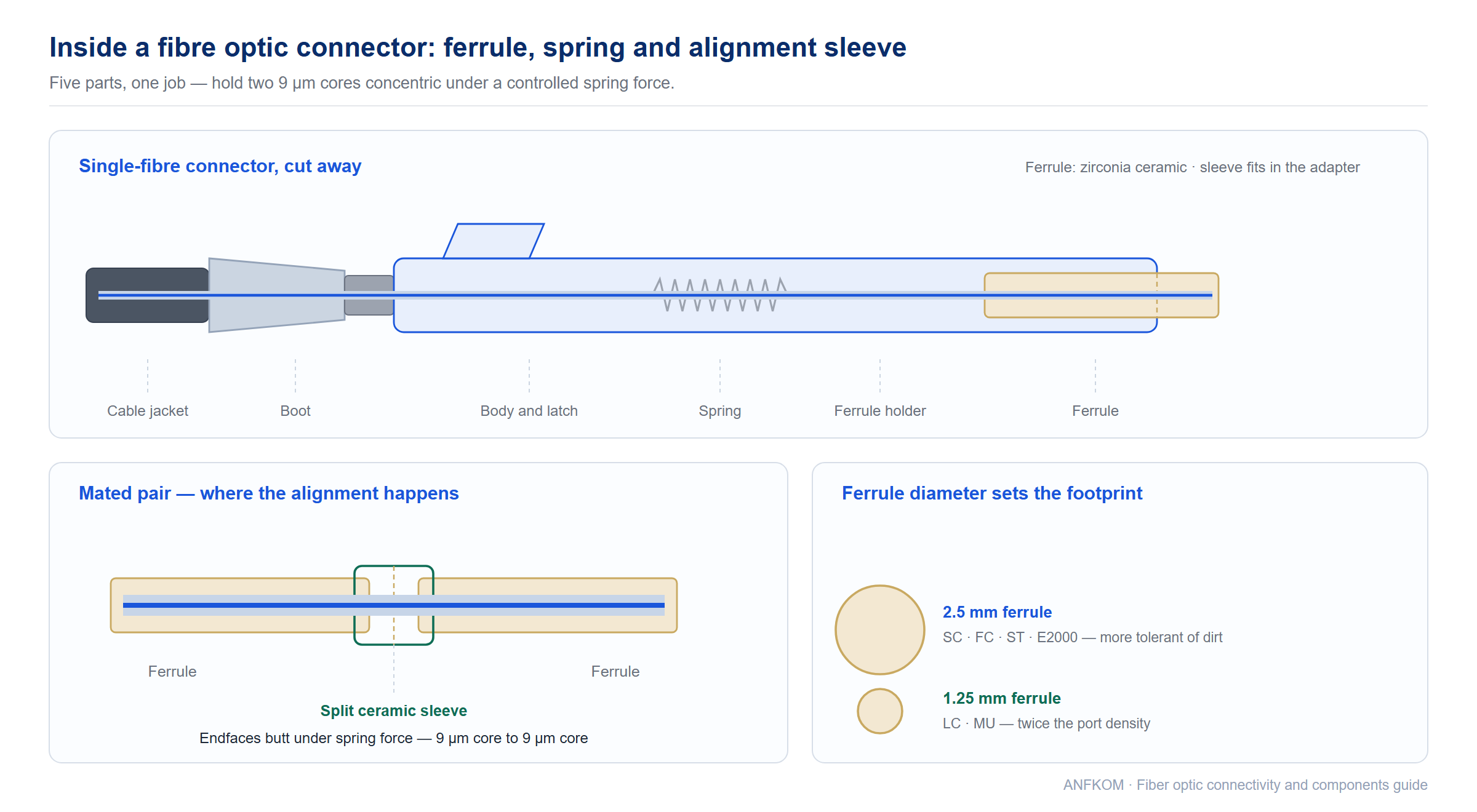
| Part | Typical material | What it does |
|---|---|---|
| Ferrule | Zirconia ceramic; metal-ceramic or stainless steel for high-power and harsh environments | Holds the fibre in a bore concentric to within a fraction of a micron and defines the endface that butts against the mating ferrule. Ceramic is used because its hardness and thermal expansion match glass closely. |
| Ferrule holder and spring | Precision-moulded plastic or metal, with a compression spring | Pushes the ferrule forward with a controlled force so the two polished endfaces maintain physical contact instead of an air gap. |
| Alignment sleeve | Split zirconia ceramic, or phosphor bronze in some low-cost designs | Lives in the adapter, not the connector. It centres the two ferrules on a common axis. This is why adapter quality matters as much as cord quality. |
| Body and latch | PBT, PEI or metal | Provides the coupling mechanism — push-pull, screw, bayonet or latch — that keeps the connector seated, and carries the keying that prevents a wrong-orientation mate. |
| Boot and strain relief | PVC, LSZH or TPU, with aramid yarn crimped to the body | Spreads bending and pulling loads into the cable jacket so they never reach the bare fibre at the ferrule tail. A patch cord fails at the boot far more often than at the endface. |
2.5 mm and 1.25 mm ferrules
Ferrule diameter is the single dimension that splits the connector world in two. The 2.5 mm family — SC, FC, ST, E2000 — was designed first and is more tolerant of contamination and of imperfect field handling, because a larger endface spreads the same dirt over more area. The 1.25 mm family — LC, MU — halves the ferrule and therefore the panel footprint, which is why almost every new high-density installation uses LC. Smaller ferrule means less spring force, tighter alignment tolerance and a genuinely higher sensitivity to a fingerprint.
Keying and tuning
Every connector has a key, notch or latch orientation that fixes its rotational position. Ferrules are never perfectly concentric, so manufacturers “tune” a connector by rotating the ferrule to the position where the fibre sits closest to the ferrule axis; the tuned position is marked on the housing. Mixing tuned and untuned connectors on a link is legal but gives away insertion loss for nothing. For LC and MU, tuning is done in steps — typically 45° or 90° — and for E2000 in 60° steps.
3. Connector families and how to choose
Twelve connector families still appear in quotations, but only five are routine. The table below is the one to keep open while reading a bill of materials; the notes after it explain where each family wins and where it does not.
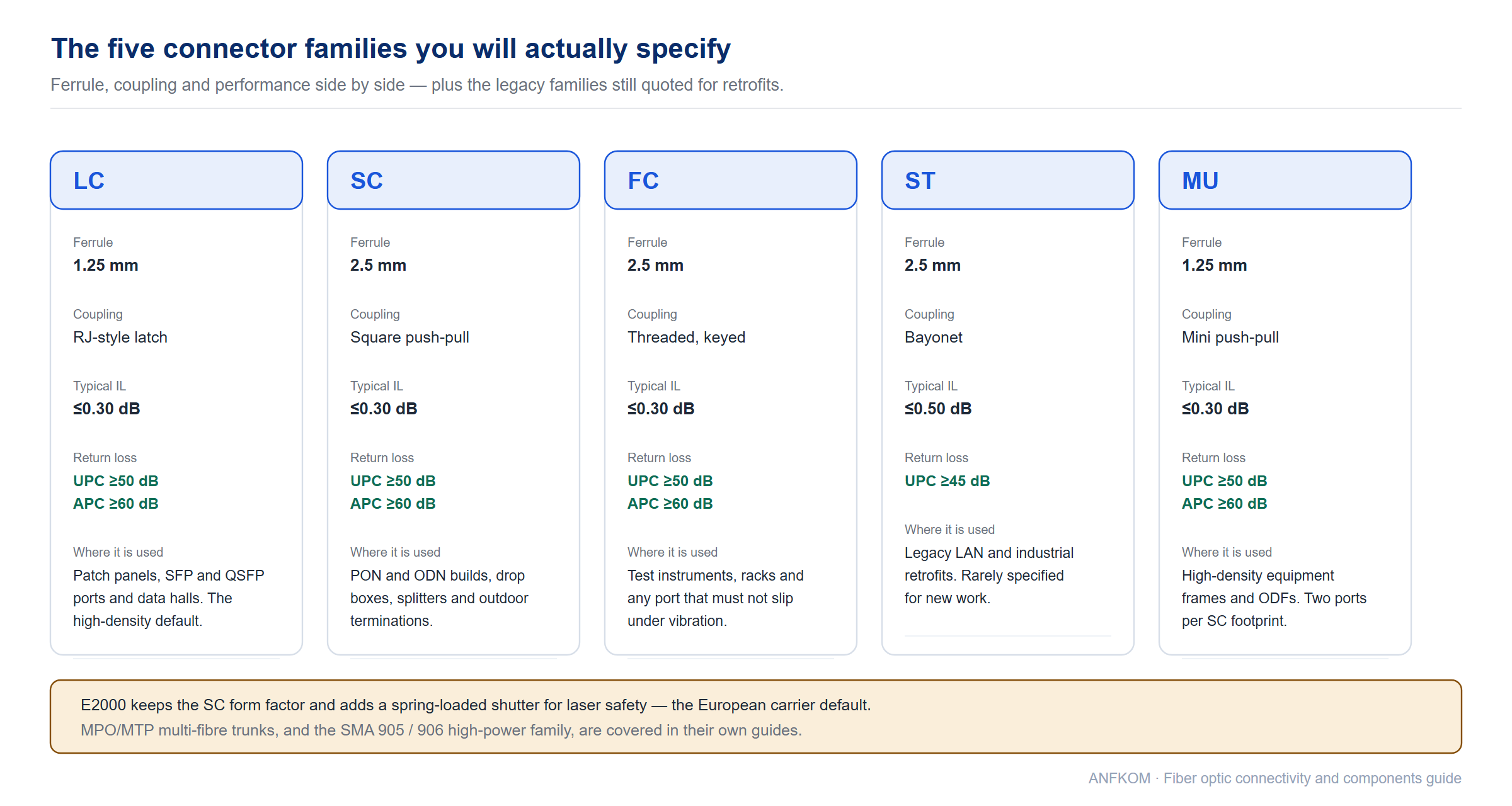
| Family | Ferrule | Coupling | Typical IL | Typical RL | Where it is used |
|---|---|---|---|---|---|
| LC | 1.25 mm | RJ-style latch, push-pull | ≤0.30 dB | UPC ≥50 dB APC ≥60 dB |
The default for patch panels, SFP/QSFP ports, data centres and modern ODFs. Smallest footprint of the single-fibre families. |
| SC | 2.5 mm | Square push-pull | ≤0.30 dB | UPC ≥50 dB APC ≥60 dB |
Dominant in PON and ODN deployments, FTTH drop boxes, splitters and outdoor terminations. Rugged, easy to clean, easy to grip with gloves. |
| FC | 2.5 mm | Threaded coupling nut, keyed | ≤0.30 dB | UPC ≥50 dB APC ≥60 dB |
Test equipment, instrument ports, telecom racks and any location with vibration or where a connector must not be pulled out accidentally. |
| ST | 2.5 mm | Bayonet, spring-loaded | ≤0.50 dB | UPC ≥45 dB | Legacy LAN and industrial installations. Still quoted for retrofits; rarely specified for new work. |
| MU | 1.25 mm | Miniature push-pull | ≤0.30 dB | UPC ≥50 dB APC ≥60 dB |
High-density equipment frames, optical modules and ODFs, especially in Japan-origin equipment. Two MU ports fit the footprint of one SC. |
| E2000 | 2.5 mm | Push-pull with side-release lever | ≤0.20 dB | UPC ≥50 dB APC ≥65 dB |
European carrier networks, DWDM terminals and any port above Class 1 laser power, because the spring-loaded shutter closes the optical path on unmating. |
| DIN | 2.5 mm | Threaded, keyed | ≤0.30 dB | APC ≥60 dB | Legacy European telecom and instrumentation, mechanically similar to FC with a different keying system. |
| D4 | 2.5 mm | Spring-loaded keyed push | ≤0.50 dB | UPC ≥45 dB | Older Japanese and European transmission equipment. Availability is now limited. |
| FDDI | 2.5 mm | Fixed duplex housing | ≤0.50 dB | UPC ≥45 dB | Legacy duplex LAN standard. Encountered only in upgrades of 1990s networks. |
| SMA 905 / 906 | 2.5 mm | Screw coupling, no key | ≤0.50 dB | PC ≥35 dB | High-power laser delivery, medical and sensing systems. SMA 905 has a straight ferrule, SMA 906 a stepped one — see our SMA 905 and SMA 906 guide. |
| MT-RJ | MT ferrule, 2 fibres | RJ-style latch, duplex | ≤0.50 dB | UPC ≥45 dB | Duplex small-form-factor LAN connector using a multi-fibre ferrule. Read the MT-RJ connector guide for the full treatment, or our MT-RJ field notes for the practical traps. |
| MPO / MTP | MT ferrule, 8–24 fibres | Spring-loaded push-pull with key | ≤0.35 dB | UPC ≥20 dB APC ≥45 dB |
Multi-fibre trunks, cassettes and 40G/100G/400G optics. Covered separately in our MPO/MTP data centre range. |
LC or SC — the decision most projects actually face
LC and SC use the same fibres, the same polish options and deliver almost the same optical performance. The choice is mechanical. LC doubles the port density and is the only sensible option in front of SFP, SFP+ and QSFP transceivers, but its 1.25 mm ferrule is more sensitive to dirt and its latch is easier to snag. SC takes twice the panel space and costs slightly more per port, but a field technician wearing gloves can seat it reliably, and a 2.5 mm endface tolerates a dirty environment better — which is why SC/APC still dominates FTTH drop and splitter work. Where you need the density of LC with the robustness of SC, MU is the compromise. If you need the full side-by-side breakdown, read LC vs SC compared.
FC, ST, E2000 and DIN — when the legacy answer is still the right one
Threaded and bayonet couplings exist because they do not come loose. FC was the standard for test instruments and long-haul terminals for two decades and remains the correct choice in rack-mounted test ports, in ODFs that see regular re-patching, and anywhere the connector must survive vibration without a latch to release. ST is the LAN equivalent but with poorer return loss. E2000 keeps the SC-like form factor and adds the safety shutter that makes it the default in European carrier networks. DIN survives in instrumentation. None of these families is obsolete — they are simply bought in hundreds rather than in thousands, and availability has to be checked before a datasheet is written.
Choosing by application
| Application | First choice | Why |
|---|---|---|
| Data centre patching and transceiver ports | LC | Port density and form-factor compatibility with SFP/QSFP cages |
| FTTH ODN, splitter boxes, drop terminations | SC/APC | Rugged, glove-friendly, lowest return loss for PON analogue and RF overlay |
| Test instruments and lab benches | FC/APC, or a hybrid adapter | Threaded coupling does not slip under cable drag; FC is the instrument-port standard |
| High-density equipment frames | MU | Two ports per SC footprint with a full 1.25 mm ferrule |
| European carrier and DWDM terminals | E2000/APC | Automatic shutter for laser safety and dust protection |
| High-power laser delivery and sensing | SMA 905 / 906 | Large ferrule geometry and metal body for thermal loading |
| 40G, 100G and 400G links | MPO/MTP | Parallel optics need 8 to 24 fibres in one mate |
Recommended products at this stage. LC connector · SC connector · FC connector · MU connector · E2000 connector · LC switchable uniboot connector
4. Polish types, return loss and why you cannot mix PC, UPC and APC
The endface of a ferrule is not flat. It is polished to a controlled spherical or angled geometry so that two mated ferrules touch glass-to-glass under spring pressure. That geometry determines how much light reflects back towards the transmitter, and return loss is the measurement of how little comes back.
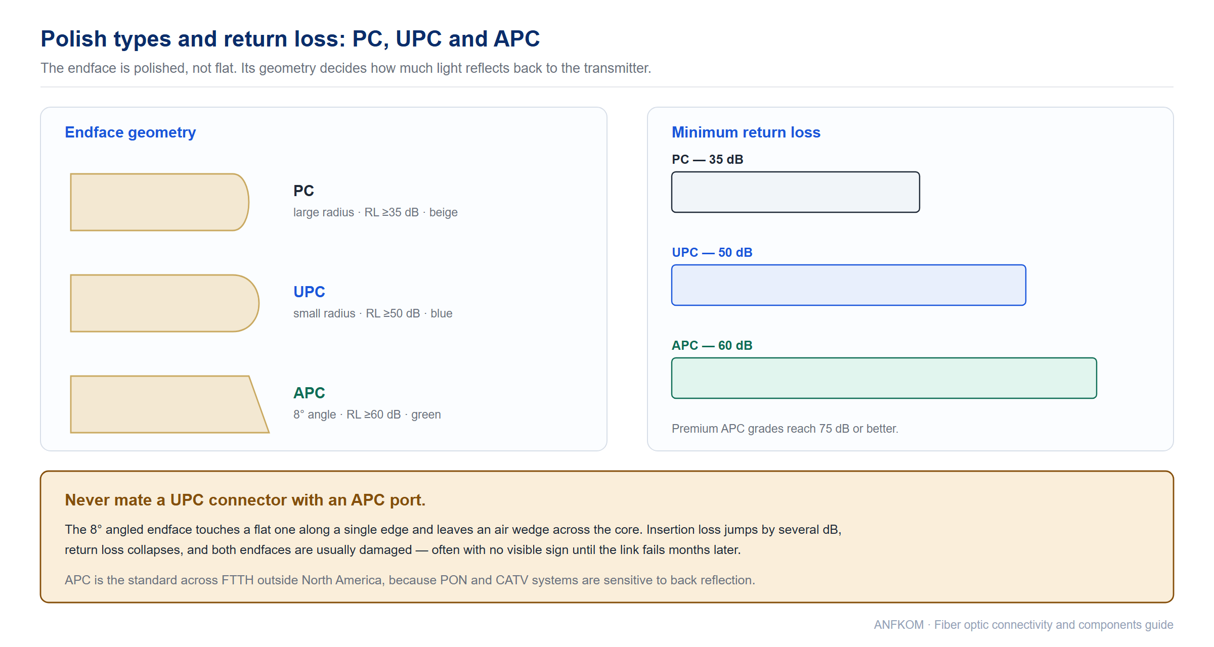
| Polish | Endface geometry | Typical return loss | Housing colour | Use it for |
|---|---|---|---|---|
| PC | Spherical, large radius | ≥35 dB | Beige (multimode) | Legacy multimode LAN links. Now largely superseded. |
| UPC | Spherical, smaller radius | ≥50 dB | Blue (single-mode) | Digital single-mode and multimode links — Ethernet, PON downstream, storage fabrics. The default choice for most new work. |
| APC | Angled 8°, radius 5–12 mm | ≥60 dB, up to 75 dB or better | Green (single-mode) | Analogue CATV and RF overlay, DWDM, high-power transmission, and any link where a reflection would disturb the laser. Standard across FTTH outside North America. |
PC and UPC are intermateable; APC is not. An 8° angled endface mated against a flat one touches on one edge and leaves an air wedge across the core. Insertion loss jumps by several dB, return loss collapses, and the two endfaces are usually damaged in the process. The damage is not visible without an inspection scope, so the fault often appears as an intermittent “bad port” months later. Keep UPC and APC patch cords in physically separate bins and colour-code the adapters.
Why return loss matters more than it looks
A reflection travelling backwards into a distributed-feedback laser shifts its emission wavelength and increases its relative intensity noise. In a digital link running at a comfortable power margin this is usually invisible; in an analogue CATV or RF-over-glass system it shows up immediately as carrier-to-noise degradation. In a DWDM system it disturbs neighbouring channels. This is why PON and CATV networks are specified in APC end to end, and why a single UPC patch cord inserted into an otherwise all-APC path can degrade a whole link budget. The detailed polish comparison, including how to convert between reflectance and return loss, is in PC, UPC and APC explained.
5. Insertion loss, durability and the grades behind the numbers
Two numbers dominate every connector datasheet, and a third decides whether the first two survive field handling. Insertion loss is the light lost through a mated pair. Return loss is the light reflected back. Endface geometry is the set of dimensions — radius of curvature, apex offset and fibre height — that make the first two reproducible rather than accidental.
| Parameter | Typical specification | Test standard |
|---|---|---|
| Insertion loss, single-mode UPC or APC | ≤0.30 dB typical ≤0.20 dB for Grade A ≤0.15 dB or better for premium/tuned grades |
IEC 61300-3-4 |
| Insertion loss, multimode | ≤0.30 dB typical at 850 nm and 1300 nm | IEC 61300-3-4 |
| Return loss, PC / UPC / APC | ≥35 dB / ≥50 dB / ≥60 dB | IEC 61300-3-6 |
| Mating durability | 500 rematings with ≤0.2 dB change; 1,000 cycles for some premium designs | Telcordia GR-326, IEC 61753-1 |
| Operating temperature | −40 °C to +75 °C for standard cords; wider for metal-bodied and high-power types | IEC 61753-1 |
| Tensile strength of the cord assembly | 100 N or better on the cable retention | IEC 61300-2-4 series |
| Ferrule geometry — radius of curvature | 10–25 mm for PC and UPC; 5–12 mm for APC | IEC 61755-3 series |
| Ferrule geometry — apex offset | ≤50 µm | IEC 61755-3 series |
| Ferrule geometry — fibre height | Controlled undercut to slight protrusion, within a few tens of nanometres | IEC 61755-3 series |
What 0.1 dB actually costs
Insertion loss is not a datasheet ornament; it multiplies. A link with twenty mated pairs at 0.30 dB each spends 6 dB of budget on connections, and the same link built with premium connectors at 0.15 dB spends 3 dB. On a GPON budget with a 1:32 splitter that difference is the margin between passing and failing the longest drop. When a network is at the edge of its reach, upgrading connector grade is usually cheaper than upgrading the splitter ratio or adding an amplifier. The loss budget arithmetic is worked through in the context of ODN design in our FTTx ODN range.
Random mating versus tuned pairs
A factory measurement is made against a reference connector of known quality. In the field, connectors mate at random, so the loss you actually see is the sum of two imperfect alignments. That is why a “0.2 dB” connector can measure 0.4 dB in service and why premium grades matter most in long ODN chains. If a project genuinely needs the lowest achievable loss, specify tuned connectors with matched keys and keep the polarity and key orientation documented — untuned rotation throws away the advantage.
Endface geometry in practice
Radius of curvature keeps the two cores in contact without over-stressing the glass; apex offset describes how far the highest point of the sphere sits from the fibre core; fibre height says whether the core protrudes or is recessed. All three are measured interferometrically on a sample basis, not on every cord, which is why a supplier’s process control matters more than the last digit on the datasheet. The full measurement set and inspection criteria are covered in ferrule endface geometry, with background on the component itself in what a fibre optic ferrule is.
Recommended products at this stage. SC connectors · LC connectors · SC with 1.2 mm boot · Ferrule inspection criteria
6. Cord cable grades: OS2, OM3, OM4 and OM5
The cord you buy is a fibre grade wrapped in a jacket, and the grade sets both the reach and the colour. Getting this wrong is the most expensive mistake in the category, because a wrong-grade cord cannot be fixed by changing a connector.
| Grade | Core | Jacket colour | Typical reach | Notes |
|---|---|---|---|---|
| OS2 | 9 µm single-mode | Yellow | 10 km and beyond; 40 km with the right optics | Lowest loss and lowest bend sensitivity of the standard grades. The default for PON, metro and long-haul patching. |
| OM3 | 50 µm multimode, laser-optimised | Aqua | 300 m at 10G, 100 m at 40G/100G | 2000 MHz·km bandwidth. Still the practical minimum for new multimode work. |
| OM4 | 50 µm multimode, laser-optimised | Aqua or violet | 550 m at 10G, 150 m at 40G/100G | 4700 MHz·km. The usual specification for in-building and campus backbones. |
| OM5 | 50 µm wideband multimode | Lime green | Same as OM4 per wavelength; more reach when short-wavelength division multiplexing is used | Designed for SWDM, which multiplexes several wavelengths over one multimode pair. See SWDM explained. |
Two rules save a lot of rework. First, never mix single-mode and multimode on one link — the core mismatch produces loss that no connector can recover. Second, keep the jacket colour convention consistent across the whole project, because it is the only field-visible indicator of grade and the only defence against a technician grabbing the wrong cord from a shared bin. The full colour sequence for fibres, tubes and ribbons is in optical fibre colour coding.
Bend-insensitive single-mode for tight enclosures
Where cords are routed around the inside of a cramped box or a wall outlet, G.657 bend-insensitive single-mode is worth specifying. It holds the same optical performance as G.652.D in a straight run but tolerates far tighter bends before the loss climbs, which is what keeps an FTTH drop working in a panel that was never designed for fibre. Bend performance is quoted in the fibre grade tables rather than in the connector specification, and it is a property of the fibre, not of the assembly.
7. Patch cords: construction, boots and options
A patch cord is the product most people mean when they say “connectivity”. The base specification is simple — connector type, polish, fibre grade, cable diameter, length — but a modern catalogue has a dozen variants because different racks fail in different ways. The table below is the practical map.
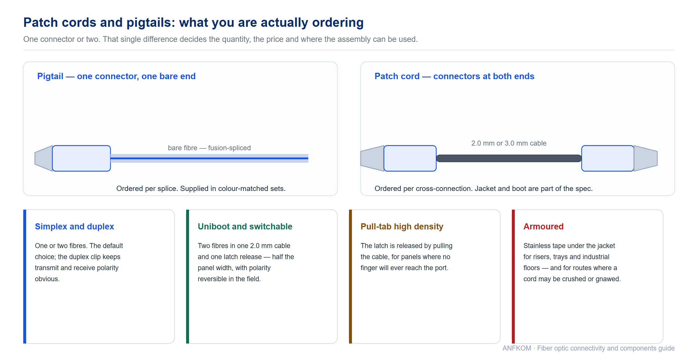
| Variant | What is different | Use it when |
|---|---|---|
| Standard simplex / duplex | 2.0 mm or 3.0 mm round cable, one or two fibres, duplex clip on LC | The default. Duplex for transmit/receive pairs, simplex for single-fibre PON drops and test leads. |
| 900 µm pigtail-style | Tight-buffered 0.9 mm, sometimes semi-tight with an easy-strip section | Inside equipment, inside splice trays, or where the cord passes through a grommet and must be spliced. |
| Uniboot | Two fibres in one 2.0 mm cable, sharing one boot and one latch release | Dense patching where a pair of duplex clips would block the neighbouring port. |
| Switchable polarity uniboot | Field-reversible A/B polarity without re-termination | Fabric builds where polarity is decided late or must be changed in service. |
| Pull-tab / push-pull HD | Extended tab so the latch is released by pulling the cable | High-density panels where there is no room for fingers — the standard answer to “you cannot reach the release”. |
| Armoured | Stainless steel tape or braid under the jacket, sometimes with a pulling eye | Riser shafts, cable trays, industrial floors, and any route where the cable may be crushed or rodent-damaged. |
| Ribbon and fan-out | 8 or 12 fibres on a ribbon, or a multi-fibre connector fanned out to simplex legs | Mass-fusion splicing and connecting a high-count trunk to individual equipment ports. |
| Multi-core breakout | One multi-fibre connector to several duplex or simplex connectors | Breaking out an MPO trunk without a cassette — see our fan-in / fan-out assemblies. |
| 90-degree | Connector body exits at a right angle | Tight wall outlets and equipment that sits flush against a cabinet side. Details in our 90-degree LC patch cord notes. |
| Curl / retractable | Coiled cord that stretches to a working length and retracts | Test benches, field kits and jumper drawers where loose leads tangle. |
| Traceable | Serial number printed and logged, so a cord can be traced to its test data | Data centres and projects with an audited test record requirement. |
| Mode conditioning | Offset launch into 62.5 µm multimode | Running 1000BASE-LX optics over legacy FDDI-grade multimode. |
| Master cord | A reference lead kept for loss measurement, not for service | Any test regime that needs a stable reference over time. |
| FTTH drop patch cord | Flat drop cable with a factory connector on one or both ends | Extending a drop through a subscriber wall box without a splice. See FTTH drop cable patch cords. |
Jacket material and fire performance
Indoor cords are usually offered in PVC, LSZH or plenum-rated compounds. PVC is the cheapest and releases halogen when it burns; LSZH emits little smoke and no corrosive halogen and is required in most public buildings and tunnels; plenum-rated cable adds a fluoropolymer or equivalent jacket that passes the plenum flame and smoke test and is mandatory in North American air-handling spaces. The rating belongs to the cable, not the connector — a premium tuned connector on the wrong jacket is still a code violation.
Length, tolerance and test data
Patch cords are made in standard lengths from 0.5 m to 50 m, with longer assemblies quoted on request. Length tolerance is normally ±1 cm on short leads and a small percentage on long ones. Two things are worth writing into an order: a per-unit insertion loss and return loss record where the project needs traceability, and the test wavelength — 1310/1550 nm for single-mode, 850/1300 nm for multimode — because a cord that passes at 1310 nm is not automatically compliant at 850 nm. Production and quality practice behind this step is described in how patch cords are produced.
Recommended products at this stage. Simplex patch cord · Duplex jumper · LC switchable uniboot · LC HD pull-tab uniboot · Armoured cord with pulling eye · OM5 patch cord
8. Pigtails and fan-out assemblies
A pigtail is terminated at one end and bare at the other, and it exists to be spliced. That single fact drives everything about how it is bought: pigtails scale with splice count, they are ordered in colour-matched sets, and the quality that matters is the buffer’s strip-ability and the ferrule’s geometry, not the boot.
| Type | Construction | When it is used |
|---|---|---|
| 0.9 mm tight buffer | Single fibre, 900 µm, easy-strip end | The standard fusion-splice tail inside a splice tray, closure or ODF. Fastest to strip and the least prone to damage in a tray. |
| 2.0 / 3.0 mm round | Single fibre in a jacketed cable | Where the pigtail leaves the enclosure and needs mechanical protection, or where it is handled rather than spliced in place. |
| 12-colour set | Twelve fibre pigtails in the TIA-598 sequence | Any tray where more than a couple of fibres are spliced. Colour matching against the cable is the primary quality control in the field. |
| Ribbon pigtail | 4, 8 or 12 fibres on one ribbon, terminated in a multi-fibre or simplex array | Mass-fusion splicing — one splice operation for a whole ribbon. |
| Fan-out pigtail | One multi-fibre connector to several 0.9 mm legs | Connecting a high-count trunk to individual ports or splices. |
| Waterproof pigtail | Hardened connector on a drop-cable tail | Tower-top and outdoor subscriber terminations where the joint must survive immersion. |
Two habits prevent most pigtail failures. Match the pigtail colour sequence to the cable colour sequence before splicing anything — a swapped pair inside a tray costs more to find than the tray costs to build. And keep the pigtail length to what the tray can actually coil, typically 1 m for a standard tray, because a pigtail that has to be forced into a bend radius will lose more in macrobend loss than the splice costs in insertion loss.
9. Adapters and couplers
An adapter is a mechanical part with an optical job: it holds two connectors and, through its alignment sleeve, keeps their ferrules concentric. It is the cheapest component in the category and the one most often cheapened until it becomes the reason a link fails. A low-grade sleeve allows the ferrules to sit off-axis, adds insertion loss, and causes wear that shows up as increasing loss over successive re-mates.
| Adapter type | Configuration | Typical application |
|---|---|---|
| Standard simplex | One port, panel-mount flange, ceramic split sleeve | ODF and patch panel bulkheads. The volume item in almost every project. |
| Duplex | Two ports in one body, LC or SC | Transmit/receive pairs; keeps polarity obvious and halves the hardware count. |
| Quad / sextuplex / octuplex | Four, six or eight LC ports in a single footprint | High-density patching where breakout ports need to sit in one panel cut-out. |
| Hybrid | Different connector on each side — LC-SC, LC-FC, SC-ST, E2000-LC | Joining two worlds without an extra patch cord: instrument to patch panel, legacy ODF to new equipment, field test set to installed plant. See our adapter overview. |
| With internal or external shutter | Spring-loaded door over the optical path | Laser safety and dust protection on exposed ports. Internal shutters sit inside the adapter; external ones are a separate clip-on door. |
| Bare-fibre adapter | Accepts a stripped fibre instead of a connector | Test and measurement — coupling a bare fibre into a power meter or OTDR port. |
| MPO adapter and plate | Keyed multi-fibre coupler, or a plate holding several | Loading MPO trunks into a cassette housing or a fixed panel. |
| Panel and rack variants | Snap-in, screw-mount, SC-footprint LC, LGX, 19-inch | The mechanical half of the specification — a correct adapter that does not fit the panel is still the wrong adapter. |
Alignment sleeve material
Zirconia ceramic is the default and is what you want for any link that will be re-mated. Phosphor bronze sleeves are cheaper and acceptable in fixed, low-cycle positions, but they wear faster and are more sensitive to contamination. Split ceramic sleeves are the reason SC and LC adapters survive thousands of matings while retaining alignment; a rigid bore design without a resilient sleeve is appropriate only for backplane and active-device receptacles, where the mechanical stop does the alignment job instead.
Adapters in the field
Most “dirty connector” faults are actually dirty adapters. An adapter collects debris on the sleeve where it cannot be seen, and every cord inserted afterwards picks that debris up on its endface. The routine that prevents it is to clean both the cord endface and the adapter sleeve at the same time, with a dedicated 1.25 mm or 2.5 mm cleaner sized to the ferrule. Adapter packs and cleaning tooling are grouped in our cleaning products range.
Recommended products at this stage. LC duplex adapter · LC quad adapter · SC adapter · Hybrid adapter LC-SC · LC to SC adapter · LC adapter with inner shutter · Bare fibre adapter
10. Attenuators
An attenuator is a deliberately lossy component. It is specified when a receiver is being overdriven — a short link with a high-power transmitter, a channel that sits too hot after amplification, or a PON where the optical power at the ONT exceeds the receiver’s overload point. Without one, the symptom is not obvious: the link works, then degrades under temperature or after an upgrade, and the fault is diagnosed as a bad transceiver. The fuller treatment, including how to size a value from a measured power reading, is in our variable optical attenuator guide.
| Type | How it works | When to choose it |
|---|---|---|
| Fixed, doped fibre | A fibre segment with a controlled dopant concentration absorbs a set amount of light | The most stable and repeatable option. Specify where the required value is known and will not change. |
| Fixed, air gap | A precisely controlled gap between two ferrule faces | Very wide attenuation range (up to 30 dB) from one design; good for high-value fixed requirements. |
| Fixed, offset / misalignment | The two cores are deliberately offset | Cheap and compact, but sensitive to the launch condition — use where stability matters less than price. |
| Variable (VOA) | Adjustable gap or a filter that can be tuned | Lab benches, commissioning, and any channel that needs to be balanced in the field rather than specified in advance. |
| Inline / female-male | A connector body with its own ferrule, plugged into a port | Fastest to fit at a receiver port or transceiver; adds one extra mated pair. |
| Adapter / bulkhead type | Fits into a panel like an adapter, attenuating the whole port | Keeping attenuation permanently with the panel instead of with the cord, so it cannot be removed by mistake. |
| Plug-in / plug-type | Larger body inserted into a dedicated socket | Equipment shelves designed for a plug-in attenuator, typically in transmission and test racks. |
| MPO attenuator | Attenuation applied to all fibres of a multi-fibre connector | Parallel-optic links where every lane needs the same margin. |
Values, tolerance and return loss
Standard values are 1, 2, 3, 5, 10, 15, 20, 25 and 30 dB. Tolerance is typically ±0.5 dB up to 10 dB and a percentage above that, and it is worth checking whether the figure is quoted for a single wavelength or across the band — an attenuator specified at 1310 nm may behave differently at 1550 nm. Return loss is the parameter that separates a good attenuator from a cheap one: in CATV, RF-over-glass and DWDM applications specify an APC attenuator with return loss of 55 dB or better, because a reflective attenuator simply moves the reflection problem instead of solving it.
11. WDM components: CWDM, DWDM and FWDM
Wavelength division multiplexing puts several signals on one fibre by giving each its own wavelength. In a components catalogue it appears as three families — coarse, dense and filter-based — and the choice between them is decided by channel count, reach and cost, not by preference.
| Family | Channel plan | Typical insertion loss | Where it is used |
|---|---|---|---|
| CWDM | 20 nm spacing, up to 18 channels across roughly 1271–1611 nm | 1.5–2.5 dB for an 8-channel mux | Metro and access capacity upgrades, campus and enterprise backbones, and any route where cost per channel matters more than channel count. Uses uncooled optics, so the whole system is cheaper. |
| DWDM | 100 GHz (about 0.8 nm) or 50 GHz spacing, up to 96 channels across the C-band near 1530–1565 nm | 2.5–3.5 dB for a 16-channel mux | Long-haul and high-capacity transport, and cable and telecom backbones where fibre count is the constraint. Needs temperature-stabilised lasers. |
| FWDM | Three fixed ports on one fibre, typically 1310 / 1490 / 1550 nm | 0.6–1.0 dB | The PON workhorse. Combines the 1490 nm downstream and 1310 nm upstream with the 1550 nm video or OTDR channel onto one drop fibre. |
Packaging matters as much as the optical design. LGX cassettes slot into standard racks and ODFs; ABS modules are used inside closures and equipment; 1U rack-mount units serve central offices where a whole mux/demux has to be terminated and labelled. Choose the package from the enclosure you already have, then the channel count from the capacity you need — reversing that order is how projects end up with a perfect 16-channel module that fits nowhere.
The relationship between multiplexers and splitters is a common source of confusion in PON design, and it is worth thirty seconds of study before ordering: a splitter divides power, a multiplexer separates wavelengths, and some boxes do both. Compare them in splitter or WDM?, and for the CD/DWDM decision read CWDM versus DWDM. A short primer on the underlying principle is in WDM in one minute.
Recommended products at this stage. CWDM mux/demux in LGX box · 1U rack-mount DWDM mux/demux · 100 GHz DWDM ABS module · Compact CWDM module · 3-port FWDM · 1×2 CWDM device
12. Splitters and couplers as components
A splitter divides one optical signal between several outputs, with no power supply and no electronics. Two technologies do it, and the difference decides the ratios and wavelengths available to you.
| Technology | How it works | Ratios available | Notes |
|---|---|---|---|
| PLC — planar lightwave circuit | A waveguide pattern etched on a silica chip | 1×2 up to 1×64, and 2×N | Broadband from 1260 to 1650 nm, uniform output, thermally stable, and the standard for PON distribution. Higher unit cost at small counts, lower at high counts. |
| FBT — fused biconic taper | Two fibres twisted, fused and tapered so light couples between them | 1×2 and 2×2, with any split ratio from 1:99 to 50:50 | Excellent for uneven taps and narrowband use, cheaper at low counts, but not practical above a few outputs. Manufacturing yield for very uneven ratios requires process control, and the coupler loss chart is not linear. |
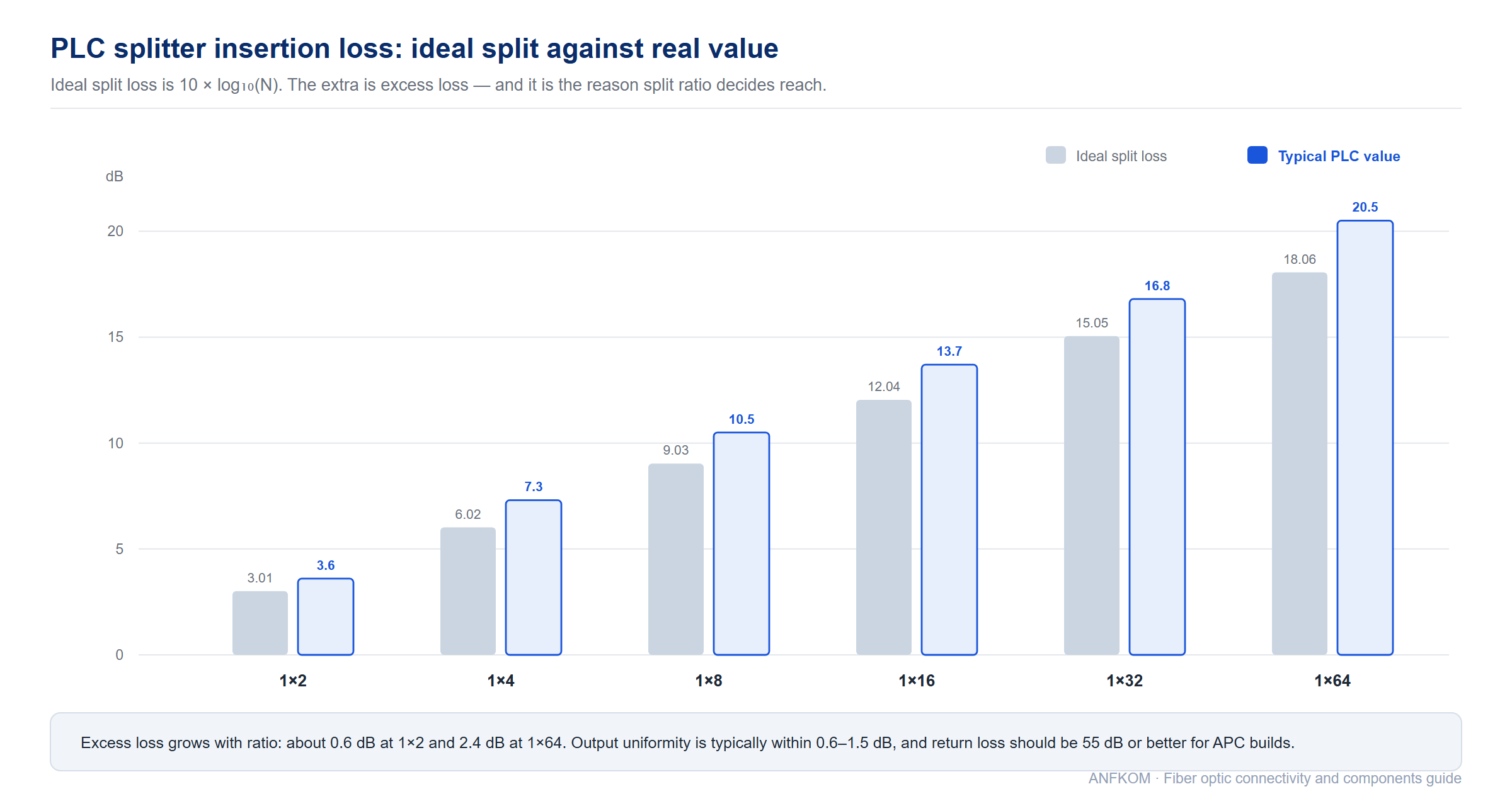
| Ratio | Ideal split loss | Typical PLC insertion loss (including excess loss) |
|---|---|---|
| 1×2 | 3.01 dB | ≤3.6 dB |
| 1×4 | 6.02 dB | ≤7.3 dB |
| 1×8 | 9.03 dB | ≤10.5 dB |
| 1×16 | 12.04 dB | ≤13.7 dB |
| 1×32 | 15.05 dB | ≤16.8 dB |
| 1×64 | 18.06 dB | ≤20.5 dB |
The gap between the two columns is excess loss, and it is why the ratio chosen at design time has a direct effect on reach. Uniformity — how evenly the outputs share power — is typically within 0.6 to 1.5 dB depending on ratio, and return loss should be 55 dB or better for APC builds. Package choice decides where the splitter can physically live: bare fibre for splicing inside a closure, stainless steel tube for a small distribution box, ABS module for a drop box, LGX cassette for a rack-mounted ODF, and 1U 19-inch units for central office frames. The technology comparison is in PLC splitter versus fused coupler.
13. Test components: loopbacks, reflectors and launch boxes
Three small components exist purely so that a link can be tested or monitored without taking it out of service. They are bought in tens rather than thousands, but a network without them cannot be commissioned cleanly.
| Component | What it does | Where it is used |
|---|---|---|
| Loopback | Connects transmit back to receive inside one housing | Checking a port, a transceiver or a patch panel without a remote end. Available as LC, SC and MPO assemblies; a standard build has insertion loss below about 1.5 dB. See loopback assemblies. |
| FBG reflector | Reflects one wavelength and passes everything else | End-of-fibre marking and PON monitoring — a 1625 nm or 1650 nm reflector at the subscriber end lets a central-office OTDR see a defined event at every drop. See fibre optic reflectors. |
| OTDR launch box / launch lead | Puts a known length of fibre ahead of the test port | Removing the dead zone at the start of a trace so the first connector and splice can be measured. A dummy bare-fibre reel does the same job for meter-side calibration. |
Two practical notes. First, loopbacks come in single-mode and multimode versions and are not interchangeable — a multimode loopback on a single-mode port produces a reflection that looks like a broken fibre. Second, a reflector is specified by wavelength and by connector/polish, and the wrong polish cannot be made to fit a UPC port. The measurement technique that makes these components useful is described in using an OTDR launch cable properly, and the units used in the results are clarified in dB or dBm?
Recommended products at this stage. LC loopback · SC loopback · FBG reflector SC/APC 1625 nm · FBG reflector SC/UPC 1650 nm · OTDR launch cable box · OTDR dummy bare fibre
14. Outdoor and hardened connectivity
Everything described so far assumes a cabinet or a rack. Outside, on a tower or in a manhole, the connector has to survive water, dust, UV, temperature cycling and being pulled. Hardened connectivity solves that by wrapping a standard optical interface in a sealed, keyed, mechanically locked shell — and by turning the weakest link from the endface into the seal.
| Family | Characteristic | Typical application |
|---|---|---|
| ODVA | Outdoor hardened duplex shell with a locking ring, IP67 or IP68 | Remote radio heads, FTTA runs, field-deployable cable — the general-purpose hardened connector. See ODVA LC armoured cords. |
| FULLAXS | Bayonet-lock hardened shell with a strain-relieved boot | Radio unit and antenna connections where connectors are installed one-handed at height. |
| PDLC | Push-on hardened duplex connector used on major 4G/5G radio platforms | FTTA jumper-to-radio interfaces at base stations. See PDLC outdoor patch cords. |
| Mini SC / OptiTap style | Single-fibre hardened push-pull connector on a drop tail | Subscriber drop terminations and pre-terminated distribution where a field splice is not wanted. See OptiTap-style drop assemblies. |
| CPRI / FTTA cords | Ruggedised duplex cords on TPU cable with defined bending tolerance | The base-band unit to radio unit run, using a specified cable diameter and connector pair. See CPRI FTTA patch cords. |
What the IP rating actually promises
IP67 means the assembly resists dust ingress and survives temporary immersion — typically 1 m for 30 minutes. IP68 means continuous immersion at a depth and duration the manufacturer declares, which is not a universal number: an IP68 rating from one vendor may mean 1.5 m for 7 days and from another 10 m for 24 hours. Always read the declared condition rather than the two digits. A second, less obvious requirement is the cable: a hardened connector on a standard indoor cord has simply moved the failure point from the shell to the jacket.
Ruggedised cords are not just connectors with a seal
Outdoor assemblies usually pair a hardened interface with an armoured or heavy-jacket cable, a strain-relief boot rated for a defined pull, and a connector body that can be handled with gloves. Where the run leaves the radio and enters a duct, the transition between the armoured tail and the cabinet patching is frequently the point of failure, because the two ends are specified by different teams. Writing the whole route into one specification — shell, cable type, pull rating and bend radius — removes that seam.
Recommended products at this stage. ODVA LC armoured patch cord · ODVA MPO/LC armoured cord · FULLAXS LC duplex cord · Huawei mini SC/APC waterproof jumper · NSN boot LC/UPC waterproof cord · ODC-LC 4-core assembly
15. Cleaning, inspection and handling
Contamination is the largest single cause of field failure in optical networks, and almost all of it is preventable. A fingerprint on a 9 µm core is a several-dB attenuator that no cleaning of the outside of the connector will touch. The routine that prevents it takes about fifteen seconds per port.
| Step | Tool | Rule |
|---|---|---|
| Inspect | Fibre inspection scope, 200× to 400×, LC and SC tips | Never mate a connector you have not looked at. Inspection zones and pass/fail criteria are defined in IEC 61300-3-35. |
| Clean the endface | One-click cleaner sized to 1.25 mm or 2.5 mm | One click per clean, and use the correct ferrule size — a 2.5 mm cleaner will not reach an LC endface. |
| Clean the adapter | Adapter cleaning stick, or the same one-click cleaner on the sleeve | Adapters hold debris where it is invisible and transfer it to every cord inserted afterwards. |
| Clean difficult contamination | Wet-then-dry with lint-free wipes and optical-grade solvent | Dry cleaning alone cannot remove cured gel or oil. Finish with a dry wipe; never leave solvent residue on the endface. |
| Inspect again | Same scope | If it is not clean, it is not ready. Re-clean rather than mate and hope. |
| Cap or mate | Dust cap, or immediate mating | An uncapped connector left in a dusty enclosure is a future fault with a known date. |
Two rules are worth repeating because they are the ones broken most often. Never reuse a cleaning tool past its rated number of cleans — a saturated wipe or a dirty clicker cartridge spreads contamination rather than removing it. And never blow on an endface, use a compressed-air can, or clean with a dry cloth; all three either add particles or generate static that attracts them. The detailed procedure, including the zone criteria and how to read a scope image, is in connector and adapter cleaning procedures.
16. How connectivity is specified and ordered
Connectivity is bought from a list, and the list is where most cost and most rework is created. Four habits make the difference between an order that arrives usable and one that arrives as a collection of near-misses.
| Habit | Why it matters |
|---|---|
| Derive quantities from the network, not from a round number | Pigtails scale with splice count, patch cords with cross-connections, adapters with ports and attenuators with receivers. Ordering everything at “1,000 pieces” guarantees a surplus of one item and a shortage of another. |
| Write the full assembly code, not just the connector | Connector type, polish, fibre grade, cable diameter, jacket material, boot type, length and tolerance. “LC/APC patch cord, 3 m” does not specify whether it is 2.0 mm or 3.0 mm, uniboot or duplex, or LSZH or PVC. |
| Specify the test regime | Whether insertion loss and return loss are measured on 100% of units or on a sample, at which wavelengths, and whether a data file accompanies the shipment. Where a project has an audited test record, this is the difference between acceptance and a rejected pallet. |
| Fix the mechanical interface early | Panel cut-out, adapter flange type, boot diameter and bend radius all constrain each other. A correct optical part that does not fit the enclosure is a change order. |
Length tolerance, packing and traceability
Standard lengths are made in 0.5 m increments; anything else is a custom build with a lead time. Tolerance is normally ±1 cm on short leads and a small percentage on long ones, and the measurement convention — over the whole assembly including both connectors, or over the cable only — should be agreed before the order is placed. Packing matters more than it sounds: cords shipped in bulk without individual bags arrive tangled and with damaged boots. Where traceability is required, the serial number and its test record must be tied together at the factory, because it cannot be reconstructed later.
17. Specification checklist
Work through the table before releasing a purchase order. Every row is a decision that will otherwise be made for you by whichever part the supplier has in stock.
| Item | What to write down |
|---|---|
| Connector family | LC, SC, FC, ST, MU, E2000 or MPO/MTP — and mating durability expectation |
| Polish | PC, UPC or APC. APC must be stated explicitly for PON and CATV work; it is not a default. |
| Ferrule and sleeve material | Zirconia ceramic ferrule and ceramic split sleeve unless there is a specific reason otherwise |
| Insertion loss grade | Maximum and typical values, and the test standard (IEC 61300-3-4) |
| Return loss | Minimum value per polish, and the test standard (IEC 61300-3-6) |
| Fibre grade | OS2, OM3, OM4 or OM5 — with jacket colour confirmation |
| Cable diameter and construction | 0.9, 2.0 or 3.0 mm; simplex or duplex; uniboot; armoured; ribbon |
| Jacket material and fire rating | PVC, LSZH or plenum-rated, with the code requirement stated |
| Boot and latch type | Standard, uniboot, switchable polarity, pull-tab, 90-degree |
| Length and tolerance | Nominal length, measurement convention and permissible deviation |
| Test regime and documentation | 100% or sample test, wavelengths, data file format, serial-number traceability |
| Environmental rating | Indoor, riser, plenum, or hardened IP67/IP68 with the declared immersion condition |
| Packing | Individual bags, reel or tray, labelling and colour coding |
| Standards and compliance | IEC 61753-1 performance category, RoHS and REACH, plus any project-specific certification |
18. Frequently asked questions
What is the difference between a patch cord and a pigtail?
A patch cord has connectors at both ends and joins two ports. A pigtail has a connector at one end and bare fibre at the other, and is fusion-spliced onto a cable fibre. Commercially, pigtails are ordered per splice and patch cords per cross-connection.
LC or SC — which should I choose?
Choose LC for density and for anything that plugs into an SFP or QSFP cage. Choose SC where the connector is handled in the field with gloves, where contamination is likely, or where an existing SC/APC architecture must be kept consistent. The optical performance is effectively the same; the decision is mechanical.
Can I connect a UPC patch cord to an APC port?
No. The 8° angled endface will not seat against a flat one. Insertion loss rises, return loss collapses and both endfaces are usually damaged. Keep UPC and APC stock physically separate and colour-code the adapters.
What insertion loss should I accept on a patch cord?
≤0.30 dB per mated pair is a normal commercial specification, ≤0.20 dB for a Grade A part and ≤0.15 dB for premium or tuned assemblies. On a long ODN chain the difference is worth paying for; on a two-connector in-rack link it usually is not.
Why are there so many hybrid adapter types?
Because installations are never uniform. A test set with FC ports has to reach an LC patch panel, and a legacy ST ODF has to be connected to new SC equipment. A hybrid adapter does that with one part instead of a special patch cord, and it keeps the transition point visible and labelled.
When do I need an attenuator?
When the optical power reaching a receiver exceeds its overload point — commonly a short link with a high-power transmitter, an amplified channel, or a PON where the drop is much shorter than the design assumed. Measure the received power first, then size the attenuator so the result sits in the middle of the receiver’s specified range rather than at its edge.
What is the difference between CWDM and DWDM?
Channel spacing and cost. CWDM uses 20 nm spacing and uncooled optics, giving up to 18 channels cheaply over metro and access distances. DWDM uses 100 GHz or 50 GHz spacing with temperature-stabilised lasers, giving up to 96 channels on one fibre for long-haul transport.
What does IP68 mean on an outdoor connector?
It means the assembly survives continuous immersion, but the depth and duration are declared by the manufacturer rather than fixed by the standard. Always ask for the declared condition, and check that the cable on the other side of the shell has an equivalent rating.
How often should connectors be cleaned?
Every time one is mated, and it is worth inspecting first — clean what needs cleaning rather than everything by habit, because a saturated wipe or a worn cleaner spreads contamination. In dusty outdoor enclosures, inspect more often than the routine suggests.
19. Related guides and tutorials
These articles go deeper on individual components. They are grouped the way a specification is written, so the section you need matches the section above.
Connectors, polish and endfaces
- Fiber optic connector — anatomy and termination
- PC, UPC and APC — polish types and why they must not be mixed
- LC vs SC — the two families you will specify most often
- MT-RJ connector — the complete guide
- MPO connector — why it matters for high-density patching
- MU connector — the small-form-factor SC
- SMA 905 and SMA 906 — high-power and sensing applications
- What a fibre optic ferrule is — the part that does the aligning
- Ferrule endface geometry — radius, apex offset and fibre height
- Ferrule inspection criteria — what passes and what does not
- Polishing problems — the defects that come out of the grinding step
- SWDM — short-wavelength division multiplexing over multimode
Patch cords, pigtails and adapters
- Choosing patch leads — a simple selection guide
- Grading patch leads — what each grade is for
- An introduction to patch leads
- Patch cord production process — how an assembly is built
- 90-degree LC patch cords — for tight outlets and flush equipment
- Multi-core fan-in and fan-out — breaking out high-count assemblies
- FTTH drop cable patch cords
- Fiber optic adapter — types and uses
- FC adapter types — the variants of the FC family
- MTRJ to LC adapter — a worked hybrid example
- Connector and adapter cleaning — the routine that prevents most field failures
Passive components and multiplexers
- Splitter or WDM? — telling the two apart on a diagram
- PLC splitter vs fused coupler — choosing the right technology
- CWDM vs DWDM — channel plans and where each belongs
- WDM in one minute — the principle in short form
- Variable optical attenuator — when and how to attenuate
- D80 connector — for high laser power applications
Testing, measurement and reference
- Using an OTDR launch cable
- dB or dBm? — the unit mix-up behind most budget mistakes
- Optical fibre colour coding — the 12-colour sequence
- Fiber optic glossary — every term used in this guide
- Browse the full tutorial library
About ANFKOM
ANFKOM manufactures fibre optic cable, passive components and FTTH accessories for telecom operators, ISPs, system integrators and distributors. Connectors, adapters, patch cords, pigtails, attenuators and WDM modules are produced and tested in-house, with insertion loss, return loss and endface inspection recorded against each batch. If you have a specification that this guide does not quite cover — a hybrid adapter, a non-standard length, a tuned grade or a hardened assembly for a specific radio platform — send it to our engineering team; we answer technical questions whether or not there is an order behind them. You can also see how we manufacture, read about quality control procedures, or learn more about the company.


