 English
 Russian
 German
 French
 Italian
 Spanish
 Partuguese
 Greek
Greek Japanese
 Korean
 Turkish
 Polish
 Arabic
MPO/MTP Cabling Guide: Connectors, Polarity, Trunk Cables and Cassettes
An MPO/MTP cable is a multi-fiber cable terminated with a single rectangular MT-ferrule connector that holds 8 to 32 fibers in one plug. It exists because parallel-optics transceivers move data over 8 or 16 fibers at once, and terminating that many fibers one at a time costs more rack space, more labor and more failure points than the network can afford.
Quick answer: MPO and MTP describe the same physical interface — MPO is the standard (IEC 61754-7, TIA-604-5), MTP is US Conec’s trademarked, tighter-tolerance version of it. Everything else about a data center MPO/MTP deployment comes down to three decisions made before anything is ordered: how many fibers the link needs (8, 12, 16 or 24), which polarity method the site is built to (A, B or C), and which loss grade the connectors must meet (standard or low loss). Get those three right and the link comes up first time.
Contents
- What MPO/MTP cabling is
- MPO vs MTP: what is actually different
- Fiber counts, connector types and speed
- Gender, keying and why a link will not mate
- Polarity: methods A, B and C
- Trunk cables: construction and system choice
- Cassettes and modules
- Patch panels and adapter plates
- Harness, breakout and conversion cables
- Testing, inspection and acceptance
- Worked example: a 100G channel loss budget
- Specification checklist
- FAQ
What MPO/MTP cabling is
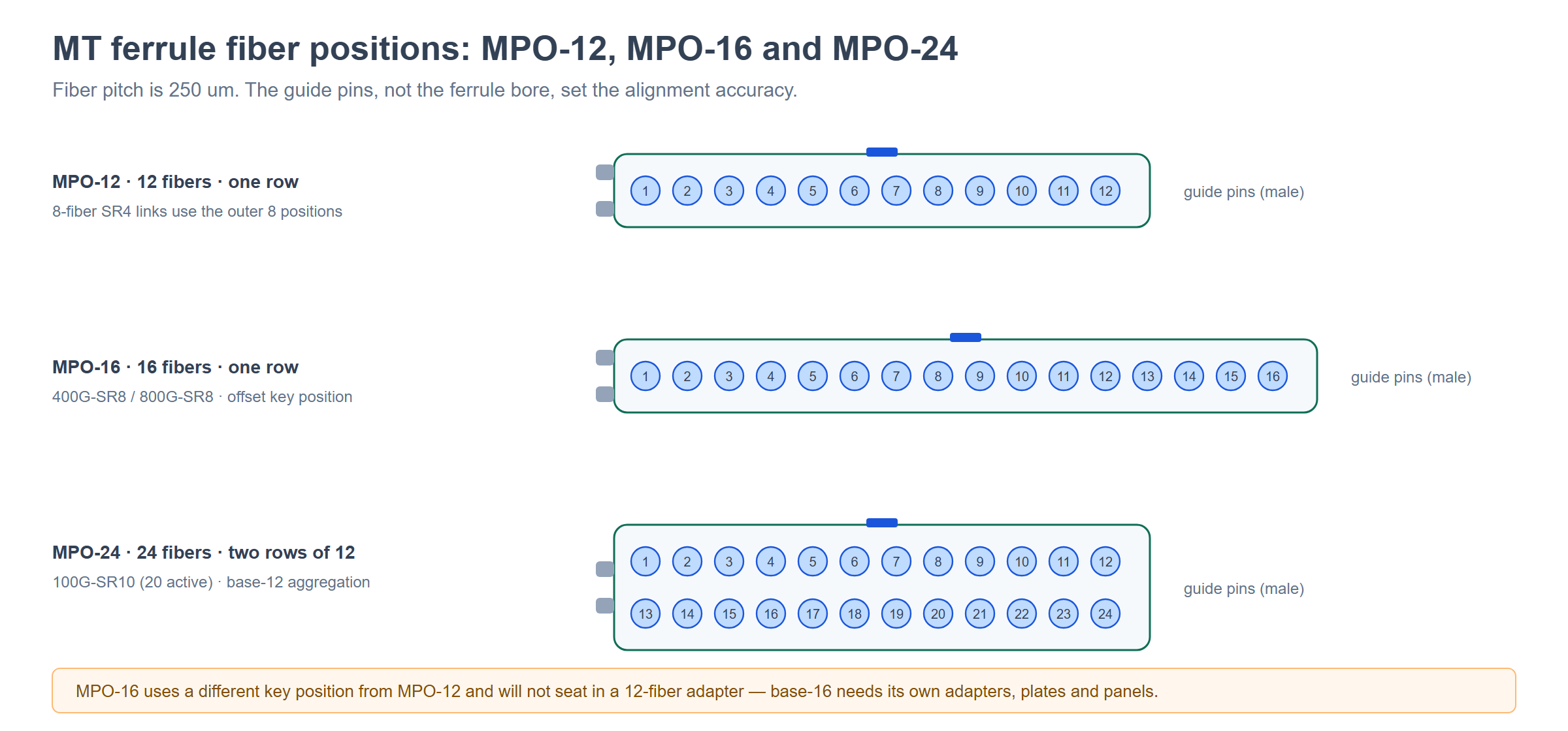
MPO stands for Multi-fiber Push-On. The connector is built around an MT ferrule — a precision-molded rectangular block, roughly 6.4 mm wide, drilled with a row of fiber holes and two guide-pin holes. The fibers sit in a single row (12 or 16 positions) or two rows (24 or 32 positions), spaced 250 µm apart, and the whole array is polished and mated as one unit.
The key difference from a duplex LC connector is where the tolerances live. An LC connector aligns one 9 µm core inside a 1.25 mm ceramic ferrule; the spring pushes the two ferrules together and the geometry does the rest. An MPO connector has to align every fiber in the array simultaneously, and the accuracy comes from the guide pins rather than from the ferrule fit. That is why MPO insertion loss is quoted per fiber channel within the connector, not as a single figure for the plug — and why the worst fiber in the array, not the average, is what passes or fails a link.
Two consequences follow, and they explain most MPO/MTP field problems:
- Loss is set by the ferrule, not by the installer. Field termination is not practical at this tolerance. MPO assemblies are factory-terminated, polished and tested, then shipped as pre-terminated trunks, harnesses and modules. The trade is less field labor for more pre-order planning.
- Order matters more than installation. Fiber count, polarity and gender are all fixed at manufacture. A 12-fiber Method A trunk and a 12-fiber Method B trunk look identical from the outside, fit the same adapters, and behave completely differently. This is why the specification, not the installation, is where MPO projects succeed or fail.
A complete MPO/MTP channel is normally assembled from four kinds of part: an MPO trunk cable that carries the fiber count across the room or between rows, MPO patch cords that make the short connections into transceivers and adapters, cassettes or harnesses that convert between the 8–24 fiber MPO world and the duplex LC/SC world, and the panels and adapter plates that hold everything in the rack. Every one of those parts carries the same three decisions — fiber count, polarity, loss grade — which is why they have to be specified as one system rather than ordered line by line.
Start from the product family
- Browse the range — MPO/MTP data center connectivity, including the six product families this guide covers
- Patch cords — MPO/MTP patch cord range from 8 to 24 fibers, OM3 to OS2
- Connectors — MPO fiber optic connector and the wider fiber optic connector range
MPO vs MTP: what is actually different
MPO and MTP are intermateable. An MTP connector plugs into an MPO adapter and mates with an MPO connector; the ferrule dimensions, guide pins and key positions come from the same standards. If you are choosing between them, you are not choosing between two systems — you are choosing between a generic part and a branded one.
MTP is a registered trademark of US Conec. It is an MPO connector with three engineering differences:
| Feature | Generic MPO | MTP (US Conec) |
|---|---|---|
| Ferrule retention | Ferrule fixed in the housing, spring applies a fixed load | Ferrule floats in the housing; a separate spring keeps constant contact pressure across the whole array |
| Guide pins | Metal pins in a molded pin holder | Metal pins in a machined holder with tighter position tolerance |
| Housing | molded body | Removable front housing; the MTP PRO variant allows gender and key orientation to be changed in the field |
| Loss grade | Standard or low loss, vendor dependent | Low loss as standard on most part numbers; Elite grades quoted with typical values per fiber |
The practical difference is consistent contact pressure across all fibers. In a fixed-ferrule MPO connector, the spring load is spread over an array; if the ferrule face is not perfectly perpendicular to the mating force, some fibers sit slightly lighter than others, and the outer positions of a 12- or 24-fiber array are usually where the high-loss channels appear. The floating-ferrule design keeps the load even, which is why MTP parts are often specified where a link is running close to its loss budget.
Three things this does not mean, which come up in almost every project:
- It does not change polarity or fiber count. An MTP trunk is still built to Method A, B or C, and still carries a fixed count of fibers. The brand tells you nothing about polarity, and polarity tells you nothing about brand.
- It does not remove the need for a loss grade. Both vendors offer standard-loss and low-loss variants. The grade, not the badge, is what decides whether a 1.9 dB channel budget closes.
- It does not make parts interchangeable at the system level. MTP and MPO mate, but a Method A trunk plus a Method B cassette is still a broken link. Brand compatibility and system compatibility are different questions.
If your procurement process is comparing suppliers rather than connector types, there are two dedicated articles on the site: the popular brands of MPO connector covers who makes what, and the competitors of MPO connector compares them on tolerances and grade. For the straight answer to the naming question, see what is the difference between MTP and MPO.
Recommended products for this stage
- MPO/MTP connector — MTP/MPO connector assemblies terminated and tested to a stated loss grade
- Field-configurable option — US Conec MTP PRO patch cord, whose gender and key orientation can be changed on site
- Service tools — US Conec MTP housing removal tool for connector work without cutting the assembly
Fiber counts, connector types and speed
Four connector counts do almost all the work in a data center: 8, 12, 16 and 24 fibers. A 32-fiber format exists for emerging 1.6T links. The count you install is decided by the transceiver, not by the cabling designer — every parallel-optics standard names a lane count, and the connector has to carry exactly those lanes.
| Connector | Fibers | Where it is used |
|---|---|---|
| MPO-8 | 8 | 8-fiber SR4 lanes. Physically an 8-fiber array, or a 12-fiber ferrule with only the outer 8 positions populated |
| MPO-12 | 12 | The default footprint. Carries 8-fiber SR4 links with 4 spare positions, and 100G-DR4 single-mode links |
| MPO-16 | 16 | 16-fiber links — 400GBASE-SR8 and 800GBASE-SR8. Uses a different key position, so it will not seat in a 12-fiber adapter |
| MPO-24 | 24 | 100GBASE-SR10 and base-12 aggregation; a 24-fiber ferrule or two 12-fiber connectors depending on the assembly |
| MPO-32 | 32 | Emerging 1.6T links |
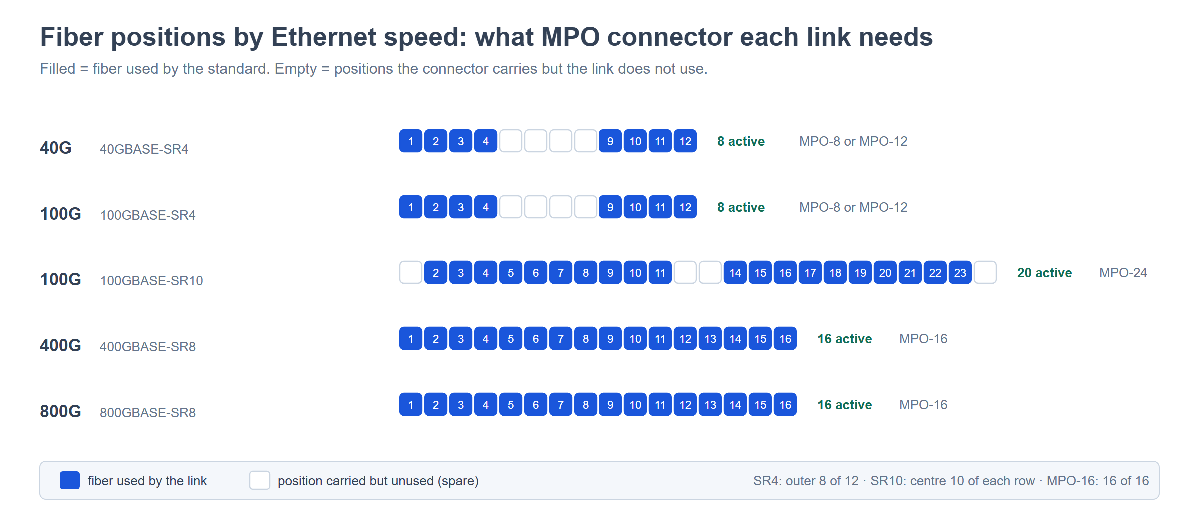
The mapping from Ethernet speed to fiber count is fixed by IEEE 802.3 and by the multi-source agreements that arrived before it. This is the table to read when you are deciding what to install:
| Ethernet | Standard | Active fibers | Connector |
|---|---|---|---|
| 40G | 40GBASE-SR4 | 8 (4 Tx + 4 Rx) | MPO-8 or MPO-12 (outer 8) |
| 100G | 100GBASE-SR4 | 8 (4 Tx + 4 Rx) | MPO-8 or MPO-12 |
| 100G | 100GBASE-SR10 | 20 (10 Tx + 10 Rx) | MPO-24 |
| 100G | 100GBASE-DR4 (single-mode) | 8 | MPO-12, APC |
| 200G | 200GBASE-SR4 | 8 | MPO-12 |
| 400G | 400GBASE-SR8 | 16 (8 Tx + 8 Rx) | MPO-16 |
| 400G | 400GBASE-DR4 (single-mode) | 8 | MPO-12, APC |
| 400G | 400GBASE-SR4.2 (BiDi/SWDM) | 8 | MPO-12 |
| 800G | 800GBASE-SR8 | 16 (8 Tx + 8 Rx) | MPO-16 |
| 800G | 800GBASE-DR8 (single-mode) | 16 | MPO-16, APC |
| 1.6T | Emerging | 16 or 32 | MPO-24 / MPO-32 |
Two decisions follow from this table, and both are worth taking slowly.
Base-12 versus base-8 versus base-16. These are three cabling systems, not three connectors. A base-12 plant moves in 12-fiber increments: 12, 24, 72, 144. A base-8 plant moves in 8-fiber increments, so an 8-fiber SR4 link uses every fiber in the path and breaks out cleanly to four duplex pairs. A base-16 plant is built around the 16-fiber connector, so one MPO-16 carries a whole 400G-SR8 link with nothing left over. The systems do not mix casually: a base-16 trunk needs base-16 cassettes and base-16 optics, and a base-12 MPO-24 trunk breaks out to base-12 MPO-12s. Since the connector you standardize on decides which speeds you can reach later without re-cabling, this is a channel-level decision rather than a per-cord one.
Do not over-specify the connector to fix a system problem. A 12-fiber trunk carrying 40G-SR4 wastes four positions per link, and a 400G-SR8 link on dual MPO-12 wastes four fibers per connector and adds a mating point. If the majority of the plant is 8-lane traffic, base-8 removes that waste; if 400G-SR8 is the target, MPO-16 removes it. Choose the base by the line rate you expect across the whole fabric, not by the first rack you are building.
Gender, keying and why a link will not mate
Every MPO connector is either pinned (male) — two metal guide pins protruding from the ferrule — or unpinned (female) — two holes for those pins. A mated pair must be one of each: pin into hole. Two pinned connectors will not seat at all, and forcing them damages the guide pins and can crack the ferrule. This is the single most common reason a pre-terminated trunk is returned to the supplier, because gender is invisible in a photograph and easy to miss on a purchase order.
| Interface | Typical gender | Consequence |
|---|---|---|
| Transceiver MPO port (QSFP+, QSFP28, QSFP-DD, OSFP) | Female (unpinned) | The patch cord reaching the optic must be male at that end |
| Cassette or module rear port | Female (unpinned) | Trunks landing on cassettes are usually male at the cassette end |
| Bulkhead adapter in a panel | Adapter only — no gender of its own | Gender is decided by the two cords arriving at it |
| Trunk cable | Male at both ends is common in base-12 cross-connects | Confirm per assembly; gender is not inferred from fiber count |
Keying is the second half of the same problem. The connector body has an offset key that indexes it in the adapter, and the adapter is built either “key-up to key-down” (Type A, straight) or “key-up to key-up” (Type B, crossover). The key positions decide which way the fiber array runs, which is exactly what polarity is about — so key orientation is not a mechanical detail that can be fixed later, it is the polarity method expressed physically.
There is one more trap worth knowing before you order. MPO-16 uses a different key position from MPO-12, so a 16-fiber connector cannot be seated in a 12-fiber adapter. That is deliberate — it prevents accidental damage from a mis-mate — but it means base-16 requires its own adapters, plates and panels. A mixed plant needs both, and the panel layout has to say which is which.
Polarity: methods A, B and C
Polarity is the mapping between the fiber positions at one end of a link and the fiber positions at the other. Get it wrong and the connector still mates, the insertion loss still passes, the light still travels — and the transceiver never negotiates, because transmit is arriving at transmit. It is a specification error, not a hardware fault, which is why it is always fixed by re-ordering rather than by re-installing.
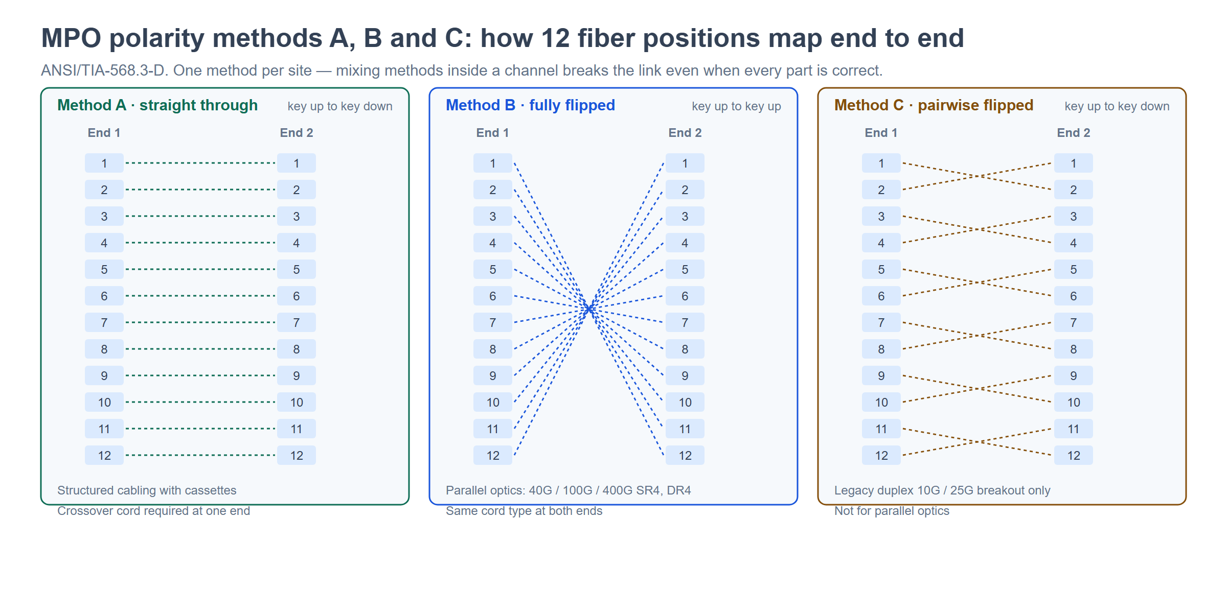
ANSI/TIA-568.3-D defines three methods. The full analysis is in our dedicated MPO polarity guide; this is the decision table:
| Method | Trunk mapping (12-fiber) | Key orientation | Patch cords | Best for |
|---|---|---|---|---|
| A — straight through | 1→1, 2→2 … 12→12 | Key-up to key-down | A crossover (A-to-B) duplex cord at one end only | Structured cabling where the polarity flip is handled inside the cassette |
| B — fully flipped | 1→12, 2→11 … 12→1 | Key-up to key-up | The same duplex cord type at both ends | Direct transceiver-to-transceiver parallel optics: 40G/100G/400G SR4, DR4 |
| C — pairwise flipped | 1↔2, 3↔4 … 11↔12 | Key-up to key-down | Standard cords at both ends | Legacy duplex 10G/25G breakout through MPO-to-LC cassettes |
Three rules that follow, and that a surprising number of projects get wrong:
- Method B is the default for new parallel-optics builds. Full reversal maps transmit lanes straight onto receive lanes at the far end, so the same patch cord type works at both ends and no special crossover jumper has to be tracked. That is why it is the recommended method for 40G, 100G and 400G SR4/DR4 links.
- Method C is not for parallel optics. Swapping adjacent pairs keeps each duplex channel’s Tx/Rx order intact but destroys the lane ordering that an 8- or 16-fiber link depends on. It belongs in duplex migration and breakout designs, not in new SR4/SR8 cabling. A supplier offering Method C for a 100G parallel-optics build is a warning sign, not a saving.
- Never mix methods inside one channel. A Method A trunk with a Method B cassette, or a Method A panel with Method C cords, will not come up even though every part is individually correct. Pick one method for the site, document it on the panel drawing, and make every trunk, cassette, adapter plate and cord consistent with it.
One constraint worth checking at order time: APC single-mode MPO connectors can only mate key-up to key-down, because the 8° endface angle is ground into one orientation. Single-mode APC systems therefore use a modified Method B arrangement rather than key-up to key-up adapters. If the trunk side is APC and the equipment side is UPC, the transition has to happen inside a cassette — not at an adapter.
Recommended products for this stage
- Adapters — MPO/MTP fiber optic adapter and MPO adapter range, in Type A and Type B key configurations
- Adapter plates — MPO fiber optic adapter plates for 6- and 12-port panel builds
- Category overview — MPO/MTP adapter category and adapter plate category
Trunk cables: construction and system choice
A trunk cable is the pre-terminated multi-fiber span that runs between two points in the fabric — row to row, cabinet to cabinet, main distribution area to equipment distribution area. It is the part of an MPO/MTP system that carries the most fiber and costs the most to change, so it is the part worth specifying properly.
Construction. Data-center trunk cable is normally a round, tight-buffered or semi-tight design: 12 or 24 fibers in a micro-core cable of around 3.0 mm, or lighter 2.0 mm constructions where bend radius and tray fill are tight. The strength member is aramid yarn; the jacket is LSZH in most new builds, with PVC and PUR as alternatives where a specific fire rating or chemical resistance is required. Ribbon constructions exist for higher counts, and an armored variant is available where a trunk leaves the rack and runs through a riser or under-floor space.
| Property | What to decide | Why it matters |
|---|---|---|
| Fiber count | 8, 12, 16, 24, 48, 72, 96, 144 | Must agree with the connector base and the cassettes at both ends |
| Fiber grade | OM3, OM4, OM5 or OS2 | Decides both the reach and the loss budget headroom for the speed you are installing |
| Cable diameter | 2.0 mm or 3.0 mm round | Bend radius, cable tray fill and patch panel strain relief |
| Jacket | LSZH, PVC, PUR, plenum-rated | Fire code in the space the cable passes through |
| Armor | armored or non-armored | Mechanical protection where the trunk leaves the rack |
| Polarity | Method A, B or C — fixed at manufacture | Cannot be changed on site without replacing the trunk |
| Gender | Male/female per end — fixed at manufacture | A gender error means the trunk goes back to the factory |
Pre-terminated versus field-terminated. MPO/MTP trunks are effectively always pre-terminated, because the ferrule tolerances cannot be reproduced in the field to the level the loss budget requires. The real decision is not “terminate or not” but how much length tolerance you can afford. Pre-terminated trunks are made to a specified length with a tolerance, and a trunk that is short cannot be extended without adding a mated pair; a trunk that is long has to be coiled somewhere with an acceptable bend radius. Measure the route — including the slack you actually need, not the slack you hope for — before releasing the order.
What goes wrong. Three failure modes account for most trunk problems, and all three are order-time decisions rather than installation ones: the wrong polarity method (link never negotiates), a gender mismatch at one end (will not mate), and standard-loss connectors on a link whose budget needed low loss (negotiates intermittently, or fails certification). The loss arithmetic is covered in the worked example below, and the selection trade-offs are set out in detail in how to choose the right MPO/MTP trunk cable.
Recommended products for this stage
- Trunk cable ranges — MTP/MPO fiber optic trunk cable, 12–144 fiber and MTP/MPO trunk cables
- High-count examples — 96-fiber OM4 MPO trunk cable
- Protected construction — armored MTP-MTP trunk cable, built on armored cable for MTP trunks
Cassettes and modules
A cassette is a pre-terminated module that converts multi-fiber MPO connectivity into conventional LC or SC ports. Inside it, a fan-out harness breaks the 8, 12 or 24 fibers out to individual duplex connectors at the front face; at the rear, one or two MPO adapters connect to the trunk. It is what lets a fabric be built on MPO trunks while the equipment ports stay LC — the standard architecture in most data centers today.
The cassette is also where polarity gets resolved in a structured-cabling design, which is why the type of adapter fitted at the rear matters as much as the fiber count:
| Cassette type | Rear adapter | Effect |
|---|---|---|
| Type A cassette | Key-up to key-down (straight) | No fiber flip at the module — pairs with a Method A trunk and a crossover cord at one end |
| Type B cassette | Key-up to key-up (crossover) | Flips the array inside the module — pairs with a Method B trunk for parallel optics |
Two constraints that are easy to miss. Method A cassettes work with both single-mode and multimode; Method B cassettes cannot be used with APC single-mode connectors, because the key-up to key-up adapter cannot accommodate the 8° angled endface. And a cassette’s polarity is a property of the module, so swapping a Type A for a Type B in one panel changes the channel mapping for every link through that panel.
Footprint. Cassettes come in two incompatible mechanical standards, and mixing them is a purchasing error rather than an installation one:
| Footprint | Dimensions (typical) | Modules per 1U panel | Capacity per 1U | Notes |
|---|---|---|---|---|
| LGX | 130 × 29 mm | 3 | Up to 72 fibers | The universal industry footprint; fits 1U, 2U and 4U LGX-compatible panels (3 / 6 / 12 modules) |
| High density (HD / U-series) | Manufacturer-specific — typically 97–102 × 33–34 mm | Vendor-specific | Vendor-specific | Smaller and denser than LGX; not interchangeable with LGX panels or plates |
A 12-fiber cassette presents 12 LC ports (6 duplex) and carries one MPO-12 at the rear. A 24-fiber cassette presents up to 24 LC ports and carries either one 24-fiber MPO or two 12-fiber MPOs. Where a splitter is needed inside the module rather than a straight patch, the same footprint is used with a PLC splitter instead of a harness — for example a 1×64 PLC splitter cassette or a standard LGX PLC splitter cassette.
A third module type, the TAP cassette, is a monitoring module rather than a patching one: it passes the link through but diverts a small, fixed proportion of the light to a separate port so a monitoring system can see live traffic without inserting an active device. It is treated as a third footprint class in most panel designs, and the differences between the three families — LGX, HD and TAP — are compared in this cassette comparison.
Recommended products for this stage
- Cassette range — MPO/MTP cassette category, with individual modules from AMC01 through AMC02, AMC05, AMC06 and AMC07
- LGX-format module — LGX MPO/MTP cassette AMC-04
- Return path — MPO loopback category for transceiver loopback test modules, plus MPO loopback fiber optic assemblies
Patch panels and adapter plates
The panel is the mechanical layer: a 1U or 2U chassis that holds cassettes or adapter plates, presents the ports at a repeatable height, protects the fibers and gives the trunk a controlled landing point. In an MPO/MTP build the capacity arithmetic is simple and worth doing before the rack elevation is drawn.
| Panel | Format | Front ports | Rear | Typical use |
|---|---|---|---|---|
| 1U MTP 72F patch panel AMPP-12 | 1U, 3 cassette slots | 72 LC | MPO / MTP | Per-rack LC presentation off MPO trunks |
| 1U MTP 72F patch panel AMPP-13 | 1U, 3 cassette slots | 72 LC | MPO / MTP | As above, alternate configuration |
| 1U MTP 96F patch panel AMPP-10 | 1U | 96 LC | MPO / MTP | Denser 1U build for high-count rows |
| MTP/MPO-LC rack mount 1U patch panel 96F AMPP-01 | 1U | 96 LC | MPO / MTP | Standard high-density LC presentation |
| MPO/MTP-LC rack mount patch panel 96F AMPP-02 | 1U | 96 LC | MPO / MTP | As above, alternate build |
| Ultra-high-density MTP/MPO patch panel AMPP-07 | 1U ultra-high density | Up to 144 LC | MPO / MTP | Maximum fibers per U |
| 1U MPO 144F patch panel AMPP08 | 1U | 144 LC | MPO / MTP | High-count spine terminations |
| 1U MPO 96F patch panel AMPP-09 | 1U | 96 LC | MPO / MTP | Mid-density 1U build |
Where cassettes are not used — typically in direct MPO-to-MPO patching, or where a panel only needs to present MPO ports — the panel is fitted with adapter plates instead. A plate holds a fixed number of MPO adapters (commonly 6, 8 or 12) in a snap-in, toolless format, and it is the plate, not the adapter, that sets the key orientation for the whole row. Plates are also where the polarity method becomes visible at a glance, so panel drawings should state Type A or Type B for every plate position.
Adapter color is worth reading as a specification check rather than a decoration. Per TIA-568 practice, aqua indicates OM3/OM4 multimode, magenta or heather violet OM4/OM5 multimode, green single-mode APC and blue single-mode UPC. A panel delivered with a mixed color set usually means a mixed specification — which is exactly what you want to catch before installation rather than after.
Recommended products for this stage
- Panel category — MPO/MTP patch panel category
- Adapter plates — MPO fiber optic adapter plates
- Related FTTx builds — fiber optic patch panel category for ODF-style panels in the same plant
Harness, breakout and conversion cables
A harness — also sold as a breakout, fan-out or hydra cable — takes one multi-fiber MPO connector and breaks it out into individual duplex LC or SC connectors, or into a different MPO count. It does the same job as a cassette, but in cable form, without a module and without a panel. The choice between the two is an architecture decision:
| Approach | Where the conversion happens | Use when |
|---|---|---|
| Cassette in a panel | In a fixed, labeled module with ports at a repeatable height | Structured cabling, many links per rack, moves and changes expected |
| Harness / breakout cable | Inline, in the cable itself | Direct connection into switch ports, small link counts, temporary or dense patching |
Breakout assemblies are specified in three parts: the MPO end (fiber count, polarity and gender), the leg end (connector type, count and length), and the breakout point (the transition from the round multi-fiber cable to individual legs, which is where bend radius and strain relief are decided). Common configurations in real builds include:
- MPO to LC duplex — the standard 8- or 12-fiber breakout, walking one MPO into four or six LC duplex pairs. See the MTP/MPO to LC breakout cable and the MTP/MPO to 4 LC duplex breakout cable.
- MPO to SC — used where the patch field is SC. See the MPO to SC breakout cable.
- Fan-out to a distribution tail — a single MPO into a length of individual legs with no panel, as in an MPO fan-out patch cord or MPO harness jumper.
- MPO to MPO count conversion — one MPO-24 converted to two MPO-12s, or one MPO to several smaller MPOs, for example a 1×MTP to 2×MTP interconnect conversion harness or the 1×MTP to 3×MTP version.
- MPO to QSFP — pre-built assemblies that fan an MPO trunk into several QSFP ports, as in MPO to QSFP 2×MTP / 3×MTP conversion harness cables.
Two specification notes that decide whether a harness works. First, the leg count must match the fiber count divided by the lane count — an 8-fiber SR4 breakout is four LC duplex pairs, and a 16-fiber SR8 breakout is eight. If the arithmetic does not close, the assembly is built for a different standard. Second, the polarity of a harness is part of the channel, not a detail: a Method B harness in a Method A channel double-flips the array and produces exactly the Tx-to-Tx failure it was bought to prevent. Order harnesses with the polarity printed on the label, and check the label at goods-in.
For links that leave the rack, the same assemblies are built in outdoor-rated versions — for example an outdoor waterproof ODVA MPO/MTP patch cord, an IP68 ODVA-MPO/LC armored patch cord, or a waterproof MPO/MTP junction box where the transition is made outside the rack.
Testing, inspection and acceptance
An MPO link has to be tested twice for two different reasons: optically, to prove the loss budget closes on every fiber; and by polarity, to prove that fiber 1 at one end arrives at the fiber the standard says it should. A link can pass the first test and fail the second, which is why test scope has to be written into the purchase order rather than decided at turn-up.
Insertion loss and return loss. Test with a light source and power meter or an OLTS, and record per-fiber results, not a single figure for the connector — the acceptance criterion is the worst channel in the array, not the average. Test bidirectionally and report the average of both directions, which is normal practice for certification. The pass/fail thresholds come from the application: a 100GBASE-SR4 channel on OM4 has a channel insertion loss budget of 1.9 dB, while the same 8-fiber link at 40GBASE-SR4 has 1.9 dB on OM3 over 100 m but only 1.5 dB on OM4 over 150 m — the standard allocates just 1.0 dB for connections and splices in that application, against 1.5 dB for 10GBASE-SR. That single number is why low-loss connectors are mandatory rather than optional on 40G/100G parallel-optics links.
The per-component maximums used to build a budget come from TIA limits: 0.75 dB for an MPO connector pair, 0.50 dB for a duplex UPC pair, 0.30 dB for a fusion or mechanical splice, and 3.5 dB/km for multimode fiber at 850 nm. Well-built channels measure far better — a clean, inspected LC pair typically reads 0.10–0.25 dB, and a good fusion splice 0.02–0.05 dB — but the maximums are what a link is certified against.
Endface inspection comes first. Inspect every endface before measuring anything, and inspect the adapter port as well as the cord end. IEC 61300-3-35 defines the pass/fail zones that the inspection scope is grading against, and contamination rather than geometry is the dominant cause of failed certification because it is invisible to the eye and easy to fix: clean, re-inspect, then measure. A dirty MPO endface is also the most common way a ferrule gets permanently damaged, since contamination is pressed into the array at every mating.
Geometry and polarity. Where a link is marginal, a multi-fiber interferometer measures ferrule endface geometry — fiber height, protrusion and coplanarity across the array — and finds the one or two fibers that sit outside tolerance. Polarity is verified separately, either by tracing with a light source or by using a dedicated polarity tester that reads all 8, 12 or 24 channels in one pass. The bench-top options on the site cover both needs: an MPO/MTP multi-fiber interferometer for geometry, a bench-top 12/24-channel insertion loss and return loss tester for per-fiber measurement, and an MPO/MTP polarity testing machine for mapping. Endface inspection uses an MPO/MTP multifunction microscope with an MPO tip.
Cleaning. Clean every MPO endface immediately before mating, with a cleaner sized for the array — a one-click tool such as the MPO one-click cleaner for connectors in service, cassette cleaning for adapters, and a polishing jig cleaner where assemblies are being reworked. Factory-side, the polish process itself is controlled by the jig and the consumables: a fiber optic MPO/MTP polishing jig sets the ferrule geometry, the polishing liquid sets the surface finish, and the APC-8000 MPO/MTP polish machine applies both consistently across a production batch. The test methods used at goods-in and at final test are set out in MTP/MPO fiber optic patch cord test methods.
Recommended products for this stage
- Measurement — IL/RL tester and multi-fiber interferometer
- Inspection — MPO/MTP microscope and MPO one-click cleaner
- Production and rework — MPO/MTP crimping machine and polishing jig
Worked example: a 100G channel loss budget
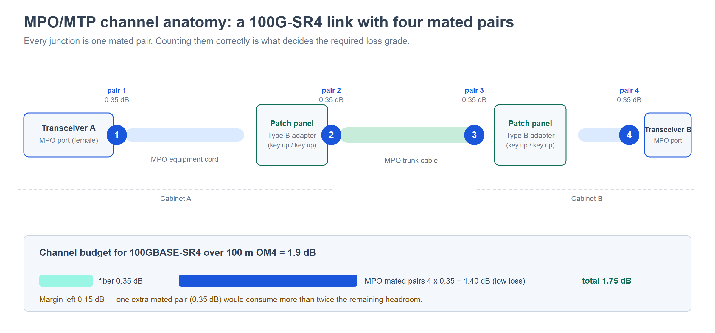
Take the most common data-center case: a 100GBASE-SR4 link over 100 m of OM4, built as a cross-connect with an MPO trunk between two cabinets and MPO equipment cords at each end. The channel has four MPO mated pairs — transceiver-to-cord and cord-to-trunk at each end. The IEEE channel insertion loss budget for this application is 1.9 dB.
| Element | Quantity | Loss each | Subtotal |
|---|---|---|---|
| OM4 fiber, 100 m at 850 nm (3.5 dB/km) | 1 | 0.35 dB | 0.35 dB |
| MPO mated pair — low loss grade (≤0.35 dB max) | 4 | 0.35 dB | 1.40 dB |
| Total with low-loss connectors | 1.75 dB | ||
| MPO mated pair — standard loss grade (≤0.60 dB max) | 4 | 0.60 dB | 2.40 dB |
| Total with standard-loss connectors | 2.75 dB |
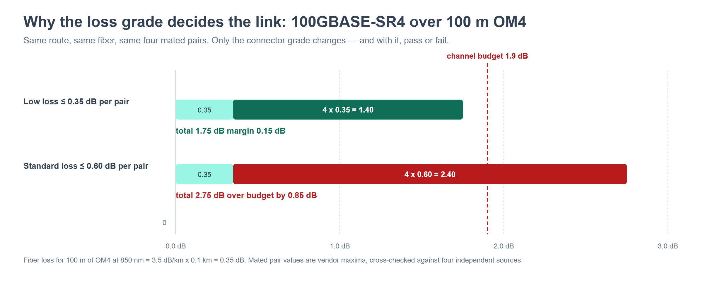
The arithmetic is the whole argument for specifying a loss grade. Low-loss connectors leave 0.15 dB of margin against a 1.9 dB budget — tight, but inside. Standard-loss connectors come in at 2.75 dB, or 0.85 dB over budget, and the link fails certification no matter how carefully it is installed. The fiber contributes 0.35 dB of the total; the connector grade decides whether the channel passes. Note also that adding a single extra mated pair costs 0.35 dB, which is more than twice the margin the low-loss build has left.
Four consequences worth carrying into the specification:
- Count the mated pairs before you choose the grade. Four pairs is a simple cross-connect. A design with cassettes at both ends, a mid-span patch panel and equipment cords can easily reach six to eight pairs, which is 2.10–2.80 dB before any fiber loss at all.
- Low loss is not a premium option on 40G and 100G — it is a requirement. The 40GBASE-SR4 OM4 application allocates only 1.0 dB for all connections and splices in the channel. Four standard-loss pairs alone would be 2.40 dB.
- Buy margin, not reach. Because the loss budget shrinks as the line rate rises, a plant built to pass at 100G is what makes a later 400G upgrade a transceiver swap rather than a re-cable. MPO-12 backbones carrying 40G today can carry higher rates by changing optics — provided the channel loss was specified with headroom.
- Verify per fiber, not per link. The worst channel in a 12-fiber array decides whether the connector passes. A link that “passes on average” has not been tested.
Specification checklist
Everything above collapses into a short list that should be complete before an MPO/MTP purchase order is released. If a line is missing, the supplier will assume, and the assumption will be whatever their standard build is — not what your site needs.
| # | Item | What to state |
|---|---|---|
| 1 | Fiber count and base | 8 / 12 / 16 / 24, and whether the plant is base-8, base-12 or base-16 |
| 2 | Fiber grade | OM3, OM4, OM5 or OS2 — driven by the standard, the reach and the upgrade path |
| 3 | Polarity method | Method A, B or C, applied consistently to trunks, cassettes, adapter plates and cords |
| 4 | Gender at each end | Male (pinned) or female (unpinned) per interface — never inferred |
| 5 | Loss grade | Standard loss or low loss, with the max IL per mated pair written into the PO |
| 6 | Polish | UPC for multimode and short-reach single-mode; APC for single-mode PON/DWDM and 100G/400G DR4 |
| 7 | Length tolerance | Cut length plus tolerance, and the slack allowance per run |
| 8 | Cassette footprint | LGX or vendor HD — not interchangeable |
| 9 | Jacket and rating | LSZH, PVC, PUR; plenum or riser rating as required by the space |
| 10 | Test report | Per-fiber IL and RL, bidirectional, supplied with every assembly |
| 11 | labeling | Polarity, fiber count and gender printed on each cord and trunk end |
| 12 | Panel drawing | Type A or Type B stated for every adapter/plate position |
Two working practices make the difference between a checklist that is used and one that is filed. First, label at goods-in, not at installation — the drawer of unlabeled MPO cords is the number one source of confusion during an outage, because two cords of the same fiber count and connector are physically indistinguishable. Second, put the polarity method on the panel drawing and nowhere else — one authoritative document, revised when the design changes, rather than a method that lives in three engineers’ memories.
FAQ
Is MTP the same as MPO?
They mate with each other and share the same ferrule dimensions, guide pins and key positions — MTP is US Conec’s trademarked MPO connector, built with a floating ferrule and a machined pin holder for tighter tolerances. In a bill of materials you can treat MTP as a premium MPO, but the polarity method, fiber count and loss grade still have to be specified separately. MTP tells you nothing about polarity.
Which polarity method should a new data center use?
Method B for direct parallel-optics links between transceivers (40G/100G/400G SR4 and DR4), and Method A where the plant is structured cabling with cassettes handling the flip. Method C belongs to legacy duplex breakout and is not suitable for parallel optics. The decision that matters most is consistency: one method for the whole site, documented on the panel drawing.
Can I change polarity in the field?
Only on UPC (flat-polish) connectors, and only with a field-configurable connector such as MTP PRO, which lets a technician reverse the key orientation with a hand tool in under a minute. Single-mode APC connectors cannot be rotated, because the 8° endface angle is ground into one orientation — for 400G DR4, FR4 and any long-reach single-mode optic, polarity must be correct at order time.
Why does my link pass insertion loss but never come up?
Polarity or gender, in that order. A polarity error mates perfectly and passes loss — transmit simply lands on transmit at the far end. A gender error usually means the connectors will not seat at all, so if the link physically assembled, suspect polarity first, then check that the trunk, cassette and cords all belong to the same method.
Do I need low-loss connectors?
On 40GBASE-SR4 and 100GBASE-SR10, the standard allocates only 1.0 dB for connections and splices across the whole channel; on 100GBASE-SR4 the channel budget is 1.9 dB. Four standard-loss MPO pairs consume 2.40 dB on their own. For parallel optics at these rates, low loss is the baseline, not an upgrade.
How much margin should a channel have?
Enough to absorb the difference between the design and what is actually installed — extra mated pairs, a re-terminated cord, a change to the route. Because one added mated pair costs 0.35 dB with low-loss parts and 0.60 dB with standard-loss parts, a channel that passes by less than one mated pair has no practical margin. Specify for the next speed up while you are ordering.
Is MPO-16 compatible with MPO-12?
No. MPO-16 uses a different key position and will not seat in a 12-fiber adapter, which prevents accidental mis-mates and ferrule damage. A plant that runs both needs separate adapters, plates and panels — and the panel drawing has to distinguish them.
Related guides and tutorials
These are the articles that go deeper on individual decisions in this guide:
- What is the difference between MTP and MPO? — the naming question, answered in full
- MPO polarity — methods A, B and C with wiring diagrams for 12- and 24-fiber arrays
- How to choose the right MPO/MTP trunk cable — fiber count, gender, polish and polarity in one place
- Difference between MTP LGX cassette, HD cassette and TAP cassette — matching the module to the panel
- What is an MPO connector and why does it matter? — the connector itself, from ferrule to housing
- MTP/MPO fiber optic patch cord test methods — what to measure and how to record it
- Data center cabling: EoR, MoR or ToR? — choosing the topology before you buy anything
- Advantages and disadvantages of OM5 fiber in the data center — where wideband multimode genuinely helps
- What equipment and consumables do you need for MPO/MTP patch cord production? — the manufacturing side of the same tolerances
- The popular brands of MPO connector and the competitors of MPO connector — who makes what, and how the grades compare
About ANFKOM
ANFKOM manufactures fiber optic cable, passive components and MPO/MTP data center connectivity for telecom operators, ISPs, system integrators and distributors. The MPO/MTP assemblies in this guide are terminated, polished and tested in-house, with per-fiber insertion loss and return loss recorded against the grade quoted on the order. If you are specifying a build and want the numbers behind a part number, send the requirement to our engineering team — we answer specification questions whether or not there is an order behind them.


