 English
 Russian
 German
 French
 Italian
 Spanish
 Partuguese
 Greek
Greek Japanese
 Korean
 Turkish
 Polish
 Arabic
Fiber Optic Cable and Accessories: Complete Selection Guide
Fiber optic cable is a cable that carries data as pulses of light through a glass core instead of electrical current through copper. A complete cable contains the optical fibers, a protective buffer, one or more strength members, water-blocking materials and an outer jacket. Cable accessories are everything that terminates, protects, joins, identifies or maintains that cable once it is in the ground, on a pole or in a rack.
Quick answer. Choose the construction first, then the fiber. Indoor runs use tight-buffered cable with an LSZH or plenum-rated jacket. Outdoor runs use loose-tube cable with a black polyethylene jacket and a water-blocking fill. Direct-buried runs add steel tape or corrugated armour, aerial runs need a self-supporting or figure-8 design, and every run needs its own accessories: closures where the cable ends, pigtails where it terminates, markers where it must be traceable, and protection hardware wherever it bends.
Contents
- 1. What a fiber optic cable is made of
- 2. Tight-buffered and loose-tube construction compared
- 3. Cable types by installation environment
- 4. Indoor cable constructions
- 5. Outdoor cable constructions
- 6. FTTH drop cable and self-supporting aerial cable
- 7. Jacket, sheath and fire ratings
- 8. Armour, strength members and rodent protection
- 9. The optical fibre grades inside the cable
- 10. Cable marking, metre marking and colour code
- 11. Fibre count, reel length and packing
- 12. What counts as a fibre optic accessory
- 13. Cable protection and routing accessories
- 14. Closures, joint boxes and terminal boxes
- 15. Pigtails, patch cords and adapters
- 16. Markers, labels and identification accessories
- 17. Tools and consumables for cable work
- 18. Specification checklist
- 19. Frequently asked questions
- 20. Related guides and tutorials
1. What a fiber optic cable is made of
A fiber optic cable is built from the inside out. The light-carrying fiber is drawn from ultra-pure silica glass, then each layer around it takes over a different job: mechanical protection, moisture blocking, tensile strength and flame performance. Understanding the layers is what makes the rest of this guide easy, because every cable type is simply a different arrangement of the same seven elements.
| Layer | Typical material | Function |
|---|---|---|
| Core | Doped silica glass, 9 µm single-mode or 50/62.5 µm multimode | Carries the light signal. Core diameter and refractive index profile determine the fibre grade and the reach. |
| Cladding | Pure silica glass, 125 µm | Lower refractive index than the core, so light is confined by total internal reflection. |
| Primary coating | Soft acrylate, 250 µm | Protects the glass surface from micro-bends and scratches. This is the “250 µm fibre” that loose tubes contain. |
| Buffer | Tight buffer (900 µm hard plastic) or a loose tube filled with gel or dry water-blocking yarn | The structural fork in cable design. Tight buffer makes each fibre directly connectorizable; a loose tube lets fibres float free of mechanical stress. |
| Strength member | Aramid yarn (Kevlar), FRP rod, steel wire, or a central steel/FRP element | Absorbs pulling tension and crush load so the glass never carries it. Also sets how stiff the cable is. |
| Water blocking | Gel fill, swellable tape/powder, or a flooded core | Stops water migrating along the cable if the jacket is damaged. Water that freezes and expands is a common cause of long-term fibre failure. |
| Outer jacket | PE (outdoor), PVC, LSZH or fluoropolymer (indoor) | UV, abrasion, chemical and flame protection. The jacket material decides which fire rating the cable can claim and where it may legally be installed. |
Single-mode and multimode in one sentence
Single-mode cable carries one light path through a 9 µm core and reaches tens of kilometres; multimode cable carries many light paths through a 50 µm core and reaches a few hundred metres, but at a lower transceiver cost. Which one belongs in your cable is decided by distance and by the equipment on each end — see section 9 for the grade tables and the links to our dedicated comparison articles.
Start from the product family. Fiber optic cable overview · Indoor cable · Outdoor cable · FTTH drop cable · Armored cable · Special cable
2. Tight-buffered and loose-tube construction compared
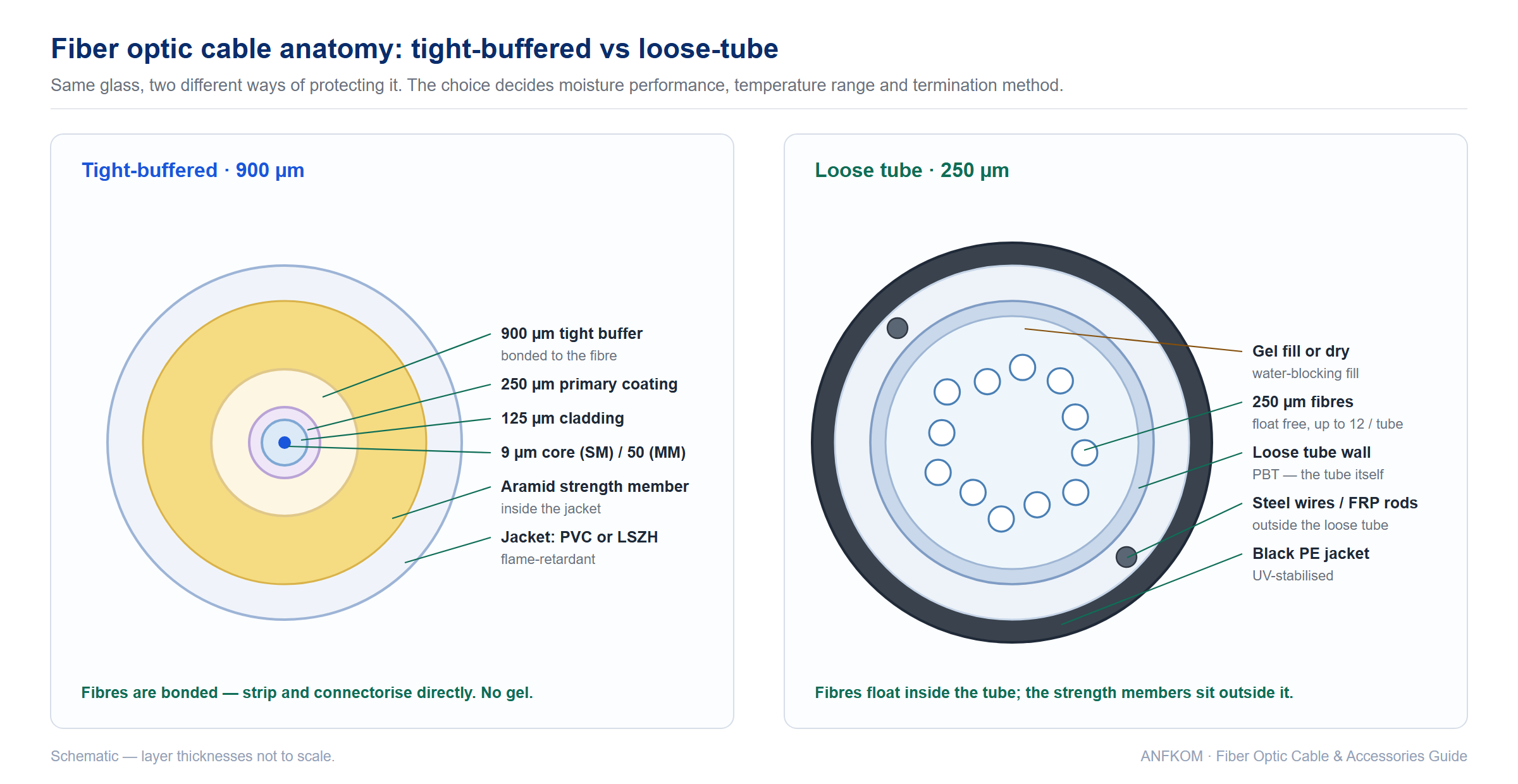
Almost every cable decision starts here. In a tight-buffered cable each fibre carries its own 900 µm plastic coating bonded directly over the 250 µm primary coating, so the fibre and its buffer move as one unit. In a loose-tube cable, up to twelve 250 µm fibres sit inside an oversized plastic tube filled with gel or dry water-blocking material, and the fibres float free. Everything else — moisture performance, temperature range, termination method, cost per fibre — follows from that one difference.
| Attribute | Loose tube (250 µm) | Tight buffered (900 µm) |
|---|---|---|
| Fibre mobility | Fibres float inside the tube; mechanical stress and thermal expansion are decoupled from the glass | Fibre is bonded to its buffer; stress on the cable reaches the fibre directly |
| Temperature range | −40 °C to +70 °C or wider; slack in the tube absorbs expansion | Narrower; best in stable indoor environments |
| Moisture protection | Gel fill or dry water-blocking — designed for wet, buried and aerial service | No gel; some indoor/outdoor designs use dry water blocking for limited runs |
| Fibre count range | 2 to several hundred (trunk and backbone) | 2 to 144 (distribution, breakout, drop, patch) |
| Termination | Splice to pigtails, or use a breakout/fan-out kit before connectorising | Stripped and connectorised directly — no gel to clean |
| Typical jacket | Black polyethylene, UV-stabilised | PVC or LSZH, flame-retardant |
| Typical environment | Duct, direct burial, aerial, long haul | Riser, plenum, equipment room, short outdoor drop |
| Field workflow | Spliced in closures and panels | Cut, stripped and terminated on site |
Where the rule breaks. Indoor/outdoor tight-buffered cable exists for campus links that must cross between buildings without a splice at each entrance. It is more rugged than standard indoor cable and removes one transition, at the cost of a larger diameter for the same fibre count. Where a project needs both — a long duct run that enters a plenum ceiling — the usual answer is loose tube to the entrance, then a splice onto an indoor-rated cable, or a single indoor/outdoor rated cable if the run is short enough to justify it.
3. Cable types by installation environment
The fastest way to specify a cable is to start from where it will be installed, because the environment dictates the construction, the jacket and the fire rating before fibre type is even discussed. The table below maps the seven common installation environments to the cable that belongs in each.
| Environment | Construction | Jacket / rating | Notes |
|---|---|---|---|
| Duct / conduit | Central or stranded loose tube, non-armoured or light armour | Black PE, outdoor | The default outdoor build. Pulling tension governs strength member choice; water-blocking is mandatory. |
| Direct burial | Loose tube with steel tape or corrugated steel armour, double-sheathed | Black PE over armour | Needs crush resistance and rodent resistance. Armour must be bonded and grounded if metallic. |
| Aerial — lashed or messenger | Loose tube lashed to a messenger wire | Black PE, UV-stabilised | Ice and wind loading act on the messenger, not the cable. |
| Aerial — self-supporting | Figure-8 with an integral messenger, or all-dielectric self-supporting (ADSS) | Black PE | No separate messenger to install. ADSS keeps the span fully dielectric near power lines. |
| Vertical riser (indoor) | Tight-buffered distribution or breakout | OFNR / CMR, or LSZH in IEC markets | Must resist floor-to-floor flame spread. Riser shafts, elevator shafts, telecom risers. |
| Plenum / air-handling | Tight-buffered, low-smoke jacket | OFNP / CMP | Required wherever the cable shares a ceiling void or raised floor with return air. |
| FTTH drop (last 100 m) | Flat butterfly tight buffer, or self-supporting figure-8 drop | LSZH or PE, often with steel or FRP strength members | Small bend radius, low cost, field-installable connectors. |
Two further cases do not fit the grid. Air-blown micro cable is installed by compressed air into pre-installed microduct rather than pulled — useful when the duct is already in place and fibre has to be added later. Our air-blowing micro cable range covers that case, and the microduct system itself is covered separately. OPGW integrates the fibres into the earth wire of a high-voltage transmission line, so it is a specialist transmission product rather than a cabling choice.
4. Indoor cable constructions
Indoor cable is optimised for tight spaces, frequent handling and fire code compliance, not for weather. All of it uses 900 µm tight-buffered fibre so it can be terminated directly on site without a splicing van.
| Construction | Fibre count | Where it is used | Why it exists |
|---|---|---|---|
| Simplex | 1 | Single device link, fibre to a sensor or outlet | Smallest possible cable; 1.6 mm, 2.0 mm or 3.0 mm jacket |
| Duplex / zipcord / twin flat | 2 | Equipment cords, workstation outlets, patch leads | Two fibres held together but splittable, so each end can be connectorised separately |
| Distribution tight buffer | 4–48 | Riser and horizontal backbone inside a building | Individually buffered fibres around a central strength member — direct termination without a fan-out kit |
| Breakout | 4–24 | Equipment room, high-vibration or heavy-handling areas | Each fibre gets its own 2.0–3.0 mm sub-jacket; rugged but bulky |
| Ribbon / flat indoor | 4–24 | Aggregation inside a building, mass-fusion splicing | Fibres arranged in a flat ribbon (about 3 mm wide for 12 fibres) for simultaneous splicing |
| Parallel / multi-core | 4–72 | Multi-fibre parallel links, short interconnect builds | Fibres side by side in one flat profile, used where each fibre carries its own lane |
| Indoor/outdoor | 4–144 | Campus runs that cross outside then continue inside | Rugged enough for duct and UV exposure but still rated for indoor flame performance |
The fibre itself is protected from handling but not from moisture, so indoor cable should not be left in a wet duct or buried. Where an indoor run must leave the building, use the indoor/outdoor variant or splice to an outdoor cable at the entry point.
Recommended products for this stage. Simplex optical fibre cable · Duplex round indoor cable · Duplex zipcord GJFJV · Distribution tight buffer GJFJV · Multi-fibre breakout indoor cable · Ribbon indoor flat cable GJFDBV
5. Outdoor cable constructions
Outdoor cable must survive water, UV, temperature cycling, rodents and pulling tension for twenty-five years. That is why the jacket is black polyethylene and the fibres live inside gel-filled or dry water-blocked tubes.
| Construction | Model family | Strength / protection | Typical route |
|---|---|---|---|
| Central loose tube, non-armoured | GYXTW, GYFXTY | Two parallel steel wires or FRP rods, outside the tube | Duct and aerial where no armour rating is needed |
| Central loose tube, aluminium tape | GYTA | Aluminium tape moisture barrier | Duct in dry or moderately wet environments |
| Central loose tube, steel tape armour | GYTS | Corrugated steel tape, bonded to the jacket | Duct and direct burial where rodent and crush protection matters |
| Non-metallic, non-armoured | GYFTY | FRP rod, all-dielectric | Aerial near power lines, lightning-prone areas; no grounding required |
| Non-metallic armour | GYFTS | Dielectric armour layer | Rodent-prone duct runs where metallic armour is not acceptable |
| Double-sheathed armoured | GYTA53, GYTY53, GYFTS | Armour between two jackets | Direct burial, river crossings, high crush load |
| Stranded loose tube, high count | GYDXTW, GJFXTKY53 | Multiple tubes stranded around a central member | Trunk ducts carrying 48–288 fibres |
| Figure-8 self-supporting | GYTC8S, GYXTC8S, GYXTC8Y | Integral messenger in the second lobe of the figure-8 | Aerial spans with no messenger wire to install |
| All-dielectric self-supporting | ADSS | Aramid and FRP only, no metal | Long aerial spans on transmission corridors |
| Unitube ribbon | GYDXTW | Ribbon stacks inside one large tube | Mass-splice backbone builds |
Model codes are not random — each position in the code describes a property of the cable. Our guide to optical cable naming rules decodes the GYTS / GYTA / GYFTY53 families position by position, and it is the fastest way to check that a quotation matches the cable you actually asked for.
Recommended products for this stage. GYTA aluminium tape cable · GYTS steel tape armoured cable · GYXTW unitube armoured cable · GYFTY non-metallic cable · GYTA53 double-sheathed cable · GYDXTW ribbon cable · GYTC8S figure-8 cable
6. FTTH drop cable and self-supporting aerial cable
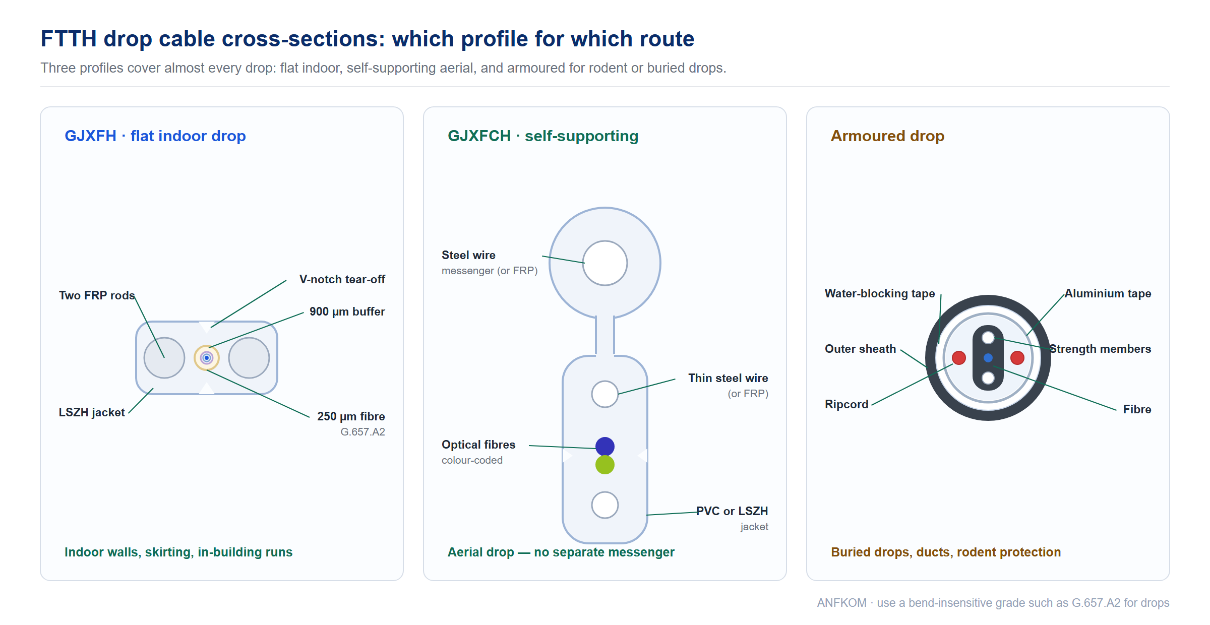
The drop segment is the last hundred metres to the subscriber, and it has its own design rules: very small bend radius, low cost per home, and a strength member strong enough to survive an aerial span or a wall drop. Three profiles dominate.
| Type | Model | Strength member | Use |
|---|---|---|---|
| Flat butterfly indoor drop | GJXFH | Two FRP rods on the sides of the flat profile | Indoor wall and skirting runs; LSZH jacket, flame retardant |
| Figure-8 self-supporting drop | GJXFCH | Steel-wire or FRP messenger above; fibre unit between two strength members below | Aerial drop between pole and building with no messenger |
| Armoured drop | — | Round profile: aluminium tape armour over water-blocking tape; strength members inside the central fibre unit, ripcords beside it | Rodent-prone drops, direct-buried drops, duct drops |
| Vertical riser extract cable | — | Rip cord and extractable fibre bundles | Rising through a building where the cable must be stripped mid-span per floor |
Drop cable is normally terminated with field-installable connectors, which means the bend radius and the fibre grade matter more than the fibre count. Use a bend-insensitive grade such as G.657.A2, keep the corner radius generous, and avoid stapling the cable tight enough to deform the flat profile — a crushed FRP rod turns into a permanent bend loss.
Recommended products for this stage. Butterfly flat indoor drop GJXFH · Aerial self-supporting drop GJXFCH · Single-armoured outdoor drop · Extract indoor cable I type · Extract distribution cable II type · All FTTH drop cable
7. Jacket, sheath and fire ratings
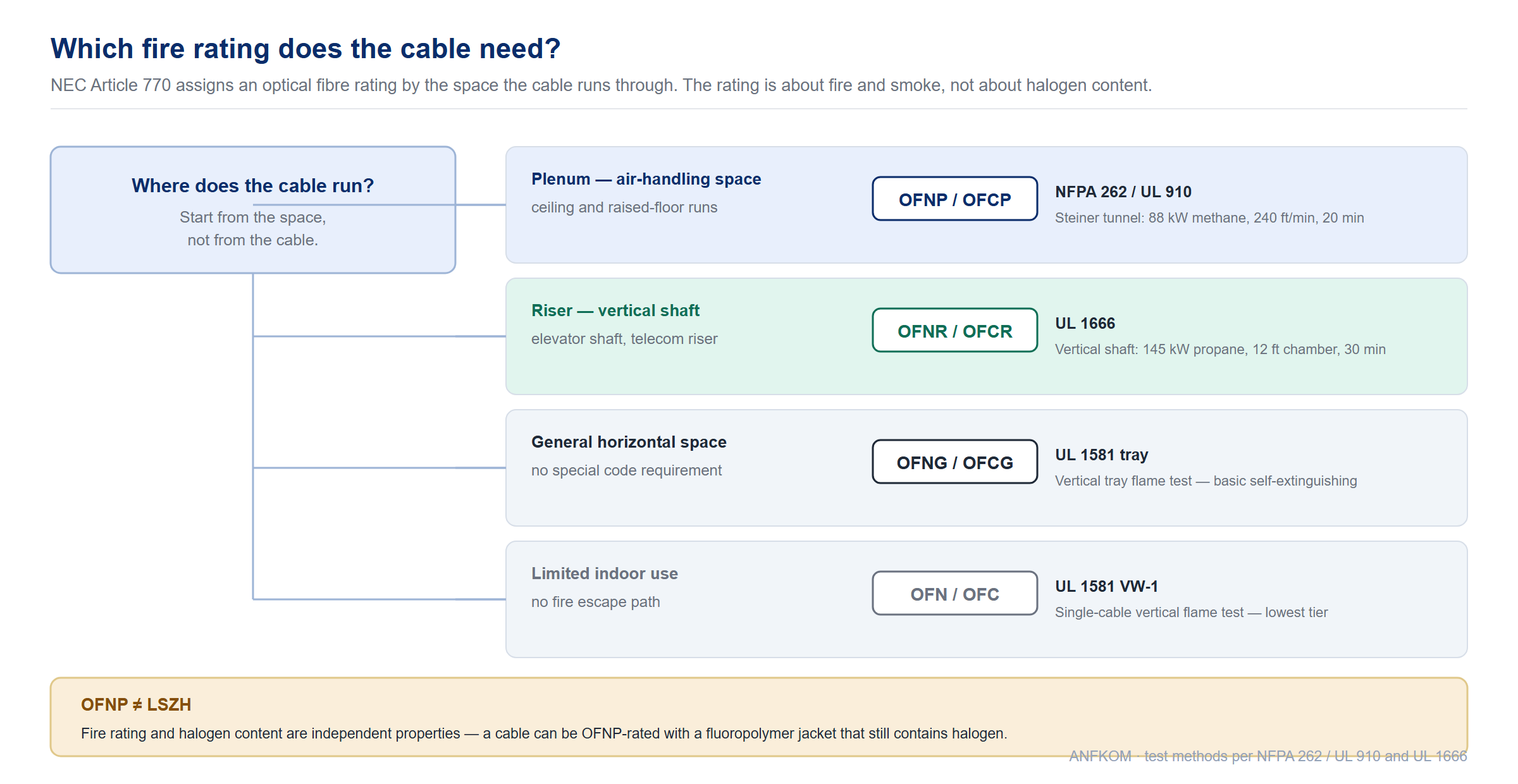
The jacket is the only part of the cable that building codes actually regulate, and it is the single most common source of a rejected shipment. Two independent properties get confused constantly: fire and smoke performance, which decides where the cable may be installed, and halogen content, which decides what happens when it burns. They are not the same thing, and a cable can satisfy one without the other.
North American ratings (NEC Article 770)
| Rating | Test standard | Test method | Where it is required |
|---|---|---|---|
| OFNP / OFCP Plenum |
NFPA 262 / UL 910 | Steiner tunnel — 88 kW methane, 240 ft/min airflow, 20 minutes; flame spread and smoke optical density measured | Air-handling spaces: ceilings used as HVAC return, raised floors used for air distribution |
| OFNR / OFCR Riser |
UL 1666 | Vertical shaft test — 145 kW propane, 12 ft chamber, 30 minutes | Vertical floor-to-floor shafts, elevator shafts, telecom risers |
| OFNG / OFCG General purpose |
UL 1581 | Vertical tray flame test | General horizontal spaces with no special code requirement |
| OFN / OFC | UL 1581 VW-1 | Single-cable vertical flame test — lowest tier | Limited indoor use where there is no fire escape path |
The suffix letter tells you whether the cable contains metal: C (conductive) means it does and may need bonding and grounding; N (non-conductive) means it does not. This is why an armoured indoor cable has a different rating code from the same construction with an FRP strength member.
Halogen content and the IEC / CPR side
In IEC and EU markets the same question is answered differently. LSZH (low smoke zero halogen) describes the compound: no halogens, so combustion produces little acid gas. It is verified by separate tests — flame spread to IEC 60332, halogen acid gas to IEC 60754, smoke density to IEC 61034. In the EU the CPR framework (EN 50575) then classes the complete cable by heat release and smoke, with sub-ratings for smoke (s1a/s1b/s1/s2/s3), flaming droplets (d0/d1/d2) and acidity (a1/a2/a3). A data-center cable is commonly specified as B2ca-s1a,d0,a1.
A specification trap worth knowing. OFNP is not the same as LSZH. Most OFNP cables achieve their rating with fluoropolymer jackets (FEP/PVDF), which contain fluorine — a halogen. LSZH means zero halogen by definition. If a project needs both, state both and ask for separate test reports: NFPA 262 for the fire rating and IEC 60754 for halogen content.
Jacket compound selection
| Compound | Property | Typical use |
|---|---|---|
| Polyethylene (PE) | Excellent UV, moisture and abrasion resistance; flammable | All outdoor cable. Black, UV-stabilised. |
| PVC | Flame-retardant, low cost, contains halogen | General purpose indoor, riser cable |
| LSZH | Low smoke, zero halogen, lower mechanical toughness than PE | Indoor riser and plenum in IEC markets, tunnels, metro, data centers with strict egress rules |
| Fluoropolymer (FEP / PVDF) | Highest smoke and flame performance, contains halogen, higher cost | OFNP plenum cable in North America |
| PU / TPU | Very high abrasion and cut resistance, flexible | Tactical, field-deployable and industrial cable |
8. Armour, strength members and rodent protection
Armour and strength members solve different problems and are frequently confused. A strength member (aramid yarn, FRP rod, central steel wire) carries tensile load during installation — it stops the cable stretching. Armour (steel tape, corrugated steel, aluminium tape, dielectric armour) resists crush, impact and rodent attack from outside the cable. A duct cable has a strength member and no armour; a direct-buried cable usually has both.
| Protection | Resists | Conductive? | Where it belongs |
|---|---|---|---|
| Aramid yarn | Tensile pulling load | No | Every cable, indoor and outdoor |
| FRP rod | Tensile load, no metal | No | All-dielectric builds, aerial near power lines |
| Aluminium tape | Moisture vapour, light rodent bite | Yes | Duct cable in wet environments (GYTA) |
| Corrugated steel tape | Crush, impact, rodent bite, moisture | Yes | Direct burial and duct (GYTS, GYTA53) |
| Interlocked / spiral armour | High crush and repeated flexing | Yes | Industrial, mining, heavy-handling routes |
| Dielectric armour | Rodent bite without metal | No | Rodent-prone ducts where metallic armour is not acceptable (GYFTS) |
| Glass yarn / nylon jacket | Rodent bite (abrasive to teeth) | No | Anti-rodent cable where armour is not wanted |
Two dedicated articles go deeper than this overview. Armored fiber optic cable: types and structure compares the armour constructions in cross-section, and anti-rodent fiber optic cable covers the non-metallic routes to the same outcome. If the route is a transmission corridor rather than a duct bank, ADSS cable explains the all-dielectric aerial option.
9. The optical fibre grades inside the cable
The jacket data sheet rarely tells you what matters most. The fibre grade inside the cable sets the reach, the loss budget and which transceivers will work. Two tables cover almost every project.
Single-mode grades
| Grade | Attenuation | Bend performance | Where it is used |
|---|---|---|---|
| G.652.D / OS2 | ≤0.35 dB/km at 1310 nm, ≤0.25 dB/km at 1550 nm typical | Standard — 10 × cable OD static, 20 × dynamic | Backbone, metro, FTTH feeder and distribution |
| G.657.A1 | Same as G.652.D | ≤0.25 dB at 1550 nm on a 15 mm mandrel, 10 turns | Drop cable, tight indoor routing |
| G.657.A2 | Same as G.652.D | ≤0.1 dB at 1550 nm on a 10 mm mandrel, 1 turn | FTTH drop at the subscriber end, wall boxes |
| G.655 | Non-zero dispersion shifted | Standard | Long-haul DWDM backbone |
Multimode grades
| Grade | Core | Bandwidth | Attenuation | Jacket colour |
|---|---|---|---|---|
| OM1 | 62.5 µm | 200 MHz·km | ≤3.5 dB/km at 850 nm, ≤1.5 at 1300 nm | Orange |
| OM2 | 50 µm | 500 MHz·km | ≤3.5 / ≤1.5 dB/km | Orange |
| OM3 | 50 µm | 2000 MHz·km | ≤3.5 / ≤1.5 dB/km | Aqua |
| OM4 | 50 µm | 4700 MHz·km | ≤3.5 / ≤1.5 dB/km | Aqua or violet |
| OM5 | 50 µm | 4700 MHz·km (wideband) | ≤3.5 / ≤1.5 dB/km | Lime green |
| OS1 / OS2 | 9 µm | — | See single-mode table above | Yellow |
Practical rule. Under 300 m, multimode is usually cheaper once transceiver cost is counted. Over 300 m, or anywhere a future capacity upgrade is likely, single-mode wins. OM1 and OM2 are legacy grades — do not include them in new builds. For a side-by-side comparison of the multimode generations, see Difference between OM1, OM2, OM3 and OM4, and for single-mode grades see Introduction to G651–G657 fiber and OS1 vs OS2.
Recommended products for this stage. Fiber optic cable by construction · Special cable (OPGW, ADSS) · ADSS aerial cable · OPGW overhead ground wire cable
10. Cable marking, metre marking and colour code
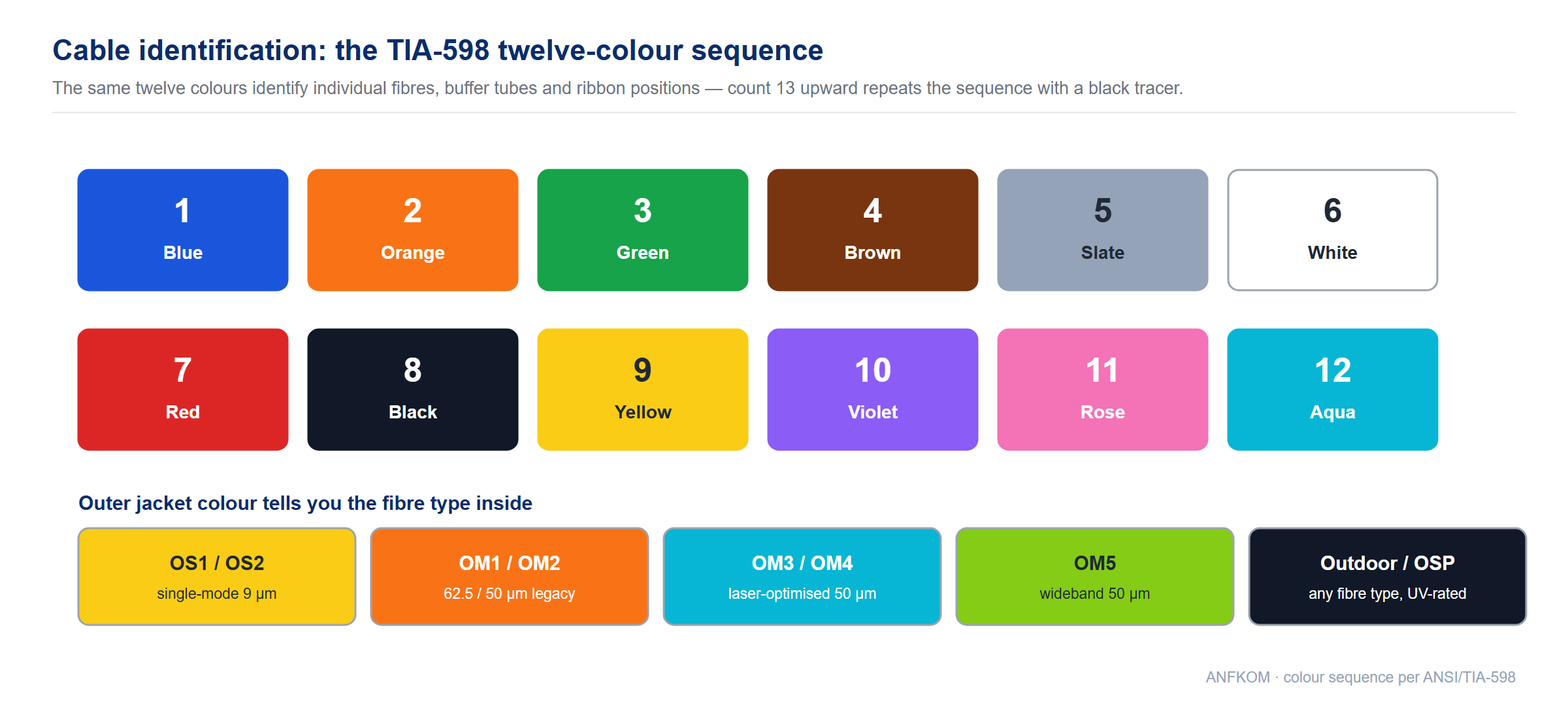
Cable identification runs on three separate systems that are often mistaken for one. Jacket legend is what is printed along the outside of the cable. Metre marking is the sequential length printed at intervals so a fault distance from an OTDR can be converted into a physical location. Colour code identifies individual fibres and tubes inside the cable. A purchase order that specifies only one of the three will produce arguments on site.
The twelve-colour sequence (TIA-598)
| Position | 1 | 2 | 3 | 4 | 5 | 6 | 7 | 8 | 9 | 10 | 11 | 12 |
|---|---|---|---|---|---|---|---|---|---|---|---|---|
| Colour | Blue | Orange | Green | Brown | Slate | White | Red | Black | Yellow | Violet | Rose | Aqua |
The same twelve colours repeat for buffer tubes and for ribbons, so tube 1 (blue) holds fibres 1–12, tube 2 (orange) holds fibres 13–24, and so on. Above twelve fibres in a group the colours repeat with a black tracer. Our optical fiber color coding article gives the full mapping including the tracer rules for high-count cables.
What belongs in the jacket legend
- Manufacturer and part number — so the cable can be re-ordered exactly
- Fibre type and count — for example
SM G.652.D 24F - Fire rating — OFNR, OFNP, or the CPR class
- Metre mark — sequential length, printed at 1 m or 2 m intervals
- Batch / lot number — links the drum back to the factory test report
- Customer branding — OEM private label, where the project is supplied under another brand
For large projects, ask for a sample of the print stream and approve it before the drum is run. Re-printing a batch is not possible once the cable is jacketed, and a wrong metre mark is a defect that only shows up during fault-finding.
11. Fibre count, reel length and packing
Fibre count is driven by the splice schedule, not by the current traffic. Sizing a feeder to exactly the equipment on day one guarantees a re-pull later; sizing it two generations ahead costs a fraction of that.
| Segment | Typical fibre count | Typical reel / drum | Reason |
|---|---|---|---|
| FTTH drop | 1, 2 or 4 | 1 km, 2 km | One or two fibres per subscriber; spare fibres are cheaper than a second drop |
| Distribution | 12, 24, 48 | 2 km, 4 km | Feeds a splitter or terminal box serving a cluster of homes |
| Feeder / backbone | 96, 144, 288 | 2 km, 4 km, wooden drum on request | Once-only installation cost; capacity added by lighting fibres, not by pulling cable |
| Data center interconnect | 8, 12, 24 (multimode or single-mode) | Pre-terminated assemblies, not bulk reels | Pre-terminated avoids field splicing in a live hall |
Reel length should be set from the duct section length plus 5–10 % slack for jointing and for the sheave runs. Ordering a single drum that is slightly longer than the longest pull is far cheaper than splicing a mid-span joint into a straight duct run. Standard packing is a wooden drum with an inner end and outer end accessible at both ends of the run.
12. What counts as a fibre optic accessory
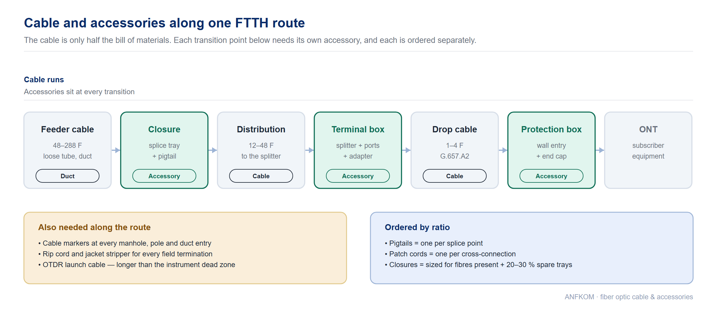
A fibre optic accessory is anything that completes the cable installation without being cable itself: the hardware that protects it, the enclosure where it terminates, the assembly that connects it, and the tooling that maintains it. Buying these separately from the cable is where most projects lose time, because the accessory specification is usually decided by the installer rather than by the buyer.
| Family | What is in it | Where to start |
|---|---|---|
| Protection and routing | Spiral wrap, protection sleeves, protection boxes, end caps, trumpet spill-out kits, bend guides, cable locks | Section 13 |
| Closures and terminal boxes | Dome closures, in-line closures, joint closures, access terminal closures, terminal boxes, ODF panels | Section 14 |
| Termination and interconnection | Pigtails, patch cords, adapters, attenuators, loopbacks, splitters | Section 15 |
| Identification | Cable markers, port bezels, labels, colour coding accessories | Section 16 |
| Tools and consumables | Jacket strippers, scribes, cleavers, cutting machines, cleaning products, test equipment | Section 17 |
Browse the accessory catalogue. Fiber optic accessories · FTTH accessories · Fiber optic tools
13. Cable protection and routing accessories
Most field failures are mechanical, and most mechanical failures happen at the places where the cable changes direction or leaves a duct. These accessories are cheap relative to the cost of a re-pull.
| Accessory | What it protects against | Where it is fitted |
|---|---|---|
| Cable split protection sleeve | Jacket splitting and abrasion at a riser transition | Where the cable leaves the duct and turns vertically |
| Drop cable protection box | Impact, UV and tampering at the subscriber entry | Wall entry point of an FTTH drop |
| Cable end cap kit / port bezel | Water ingress at the end of an un-terminated cable; port identification | Spare ducts and reserved cable ends; panel ports |
| Trumpet spill-out kit | Bend radius violation where fibres leave the cable or the closure | Closure entry ports and breakout points |
| Cable connector / junction | Mechanical joint between cable sections | Duct-to-cable transitions |
| Fibreglass duct rodder | Prevents cable being pushed blind into a blocked duct | Rodding and proving a duct before the pull |
Two habits prevent most of this category of damage. First, verify the minimum bend radius at every change of direction — the installed (static) limit is typically 10 × the cable outside diameter for a standard cable and 20 × while it is being pulled. Second, never pull a cable around a corner without a sheave or a bend guide; a bare duct edge acts as a blade under tension.
14. Closures, joint boxes and terminal boxes
Every cable run ends somewhere, and the enclosure it ends in decides whether the splice survives. Closures are selected by splice capacity, by the number and size of cable entry ports, by whether they will be buried, pole-mounted or in a handhole, and by the sealing method — heat-shrink, mechanical or gel.
| Enclosure | Mounting | Typical capacity | Where it is used |
|---|---|---|---|
| Dome closure | Pole, manhole, direct burial | Up to 96–144 splices | Trunk and feeder joints, aerial and buried |
| In-line closure | Duct, direct burial | 12–96 splices | Straight-through joints where the cable continues in both directions |
| Access terminal closure | Pole, wall | 1–12 splices | Where a feeder cable drops a service to a subscriber |
| Splitter dome closure | Pole, manhole | Splitter plus splice trays | Combines a PLC splitter and the splice joints in one enclosure |
| ODF panel | 19″ rack | 12–144 ports | Central office and equipment room termination |
| Splice closure range | All | — | Full catalogue of dome and flat closures |
Selection rule. Size the closure for the fibres present plus a 20–30 % spare tray capacity, and count the entry ports you will actually need — including the spare duct you reserved for a future cable. A closure that is full on the day it is installed cannot accept the capacity growth that the feeder cable was sized for.
Recommended products for this stage. Closure AFC-M12AX · Closure AFC-M11AX · Joint closure AFC-06A · Joint closure AFC-M6AX · Access terminal closure AFC-004 · ODF patch panel with door
15. Pigtails, patch cords and adapters
A pigtail ends in a connector at one end and bare fibre at the other, and it is fusion-spliced onto a cable fibre inside a splice tray. A patch cord has connectors at both ends and connects two ports. The distinction matters commercially because the two are ordered in completely different quantities: pigtails scale with splice count, patch cords with port count.
| Assembly | Construction | Typical buffer | Ordered by |
|---|---|---|---|
| Pigtail | One connector, one bare fibre end | 0.9 mm tight buffer | Splice count — one per splice point |
| Patch cord | Connectors both ends | 2.0 mm or 3.0 mm | Port count — one per cross-connection |
| Ribbon pigtail | 4 / 8 / 12 fibres on one ribbon | Ribbon | Mass-fusion splicing in a ribbon tray |
| Fan-out / breakout pigtail | One multi-fibre connector to several single-fibre connectors | 0.9 mm legs | Connecting a high-density trunk to simplex equipment ports |
Colour coding does most of the quality control here. If the pigtail colours match the cable fibre colours, a mistake shows up immediately in the splice tray rather than at the far end of the link. Our FTTH pigtail and patch cord ranges are supplied in single-mode and multimode with LC, SC, FC, ST and E2000 options.
Recommended products for this stage. 12-colour pigtail set · Simplex 2.0 mm pigtail · Multi-core fan-out pigtails · E2000 pigtail · Fiber optic connectors · Fiber optic adapters
16. Markers, labels and identification accessories
Identification is a procurement decision, not an installer preference. The moment a network has more than one cable in a duct or more than one port in a panel, unmarked hardware starts costing money in fault-finding time.
| Item | What it identifies | Where it goes |
|---|---|---|
| Cable marker | The route, the cable number and the owner | Every manhole, pole and duct entry |
| Port bezel / label plate | Which panel port is which | Front of every patch panel and ODF |
| Colour-coded pigtails | Fibre position, matching TIA-598 | Splice trays and patch panels |
| Metre marking on the jacket | Physical distance along the route | Printed by the cable manufacturer |
The practical standard is that a technician should be able to stand at any joint, read the marking, and know which cable they are holding without opening anything. Specify the marking scheme in the purchase order alongside the cable itself — retro-fitting markers to a buried route is expensive.
17. Tools and consumables for cable work
The tooling list follows the workflow: strip the jacket, prepare the fibre, splice or terminate it, clean it, then test it. Every one of these steps has a consumable that runs out, and a project that orders tools but not consumables stalls in the first week.
| Tool / consumable | Task | Notes |
|---|---|---|
| Drop cable jacket stripper | Removing the flat drop jacket without nicking the fibre | Matched to the drop profile, not a generic stripper |
| Cable stripper | Opening round indoor and outdoor cable | Adjustable blade depth prevents fibre damage |
| Scribe / cleaver pen | Scribing and cutting bare fibre | For field drops where a bench cleaver is not available |
| Automatic cable cutting machine | Cutting to length in production | Factory and patch-cord production line use |
| Cleaning products | Removing gel, dirt and dust from fibres and connectors | Cleanliness is the single largest cause of avoidable loss |
| Test equipment | OTDR, loss test set, visual fault locator, inspection scope | Acceptance testing needs a launch cable and a documented trace |
One test accessory deserves its own mention. An OTDR cannot measure the first and last few hundred metres of a link accurately, because the connector at the instrument is still settling. A launch cable provides that distance, and its length must be longer than the OTDR dead zone. Our guide on how to use the OTDR launch cable properly covers the length calculation and the box options.
18. Specification checklist
Work down this list before sending a cable enquiry. Each line is a decision the factory has to make, and a missing line is what turns into a wrong shipment.
| Decision | What to state |
|---|---|
| Application | Duct / direct burial / aerial / riser / plenum / drop |
| Construction | Tight buffered or loose tube; central or stranded; armoured or not |
| Fibre grade | G.652.D, G.657.A1/A2, G.655, OM3, OM4, OM5 |
| Fibre count | Exact count, plus spare capacity if the feeder is being sized for growth |
| Jacket | PE / PVC / LSZH / fluoropolymer, and the fire rating required by the installing country |
| Strength and armour | Aramid, FRP, steel tape, corrugated steel, dielectric armour |
| Water blocking | Gel-filled or dry — dry saves significant splicing time |
| Marking | Legend content, metre marking interval, OEM branding if required |
| Reel length and packing | Metres per drum, drum type, whether both ends must be accessible |
| Test reports | Attenuation and geometry data per fibre, plus fire-rating certificates |
| Accessories | Closures, pigtails, markers and protection hardware ordered together with the cable |
19. Frequently asked questions
What is the difference between indoor and outdoor fiber optic cable?
Indoor cable uses 900 µm tight-buffered fibres with a flame-retardant PVC or LSZH jacket, so it can be terminated directly and passes building fire codes. Outdoor cable uses 250 µm fibres inside gel-filled or dry water-blocked loose tubes with a black polyethylene jacket, so it survives moisture, UV and temperature cycling but is flammable and must not be run inside a building. Indoor/outdoor cable combines both, and is used where a campus run crosses between buildings.
How many fibres should I order for a new build?
Size from the splice schedule two generations ahead, not from current traffic. A typical FTTH drop is 1–4 fibres, a distribution cable 12–48, and a feeder 96–288. The incremental cost of extra fibres in a loose-tube cable is small compared with the cost of re-pulling a duct, and unlit fibres do not need equipment.
Is OFNP the same as LSZH?
No. OFNP describes a North American plenum fire rating tested to NFPA 262. LSZH describes the jacket compound and means it contains no halogens. Many OFNP cables use fluoropolymer jackets that do contain halogens, so a cable can be OFNP and not LSZH. If a specification requires both, state both and ask for NFPA 262 and IEC 60754 test reports separately.
Do I need armoured cable?
Use armour where the cable is at risk of crush, impact or rodent damage: direct burial, rocky duct, industrial sites and rodent-prone routes. Where metal is not acceptable — aerial spans near power lines, or sites where grounding is impractical — a dielectric armour or an anti-rodent jacket gives similar protection without conductivity. Our armored cable types guide compares the options.
Which accessories do I need for a simple FTTH drop?
The drop cable itself, a protection box at the subscriber wall entry, a marker at the pole or duct entry, a terminal or access closure where the drop is spliced to the distribution cable, and a pigtail per splice. In most builds, a field-installable connector removes the splice entirely at the subscriber end.
How do I check that a delivered cable matches the order?
Read the jacket legend against the purchase order: fibre count, fibre grade, fire rating, batch number and metre marking. Then check the factory test report for attenuation and geometry, and confirm the drum count and reel lengths. Our cable inspection criteria article lists the acceptance checks in order.
Why does my cable say GYTA and another says GYTS?
The letters encode the construction. In the GY series, each position describes a property — outdoor use, loose tube, the strength member material, the armour type and the jacket. An aluminium tape barrier (GYTA) and a corrugated steel tape armour (GYTS) are different products for different environments, even at the same fibre count. The naming rules article decodes every position.
20. Related guides and tutorials
- What is fiber optic cable? Types and structure
- Types of fiber optic cable
- Armored fiber optic cable: types and structure
- ADSS all-dielectric self-supporting cable
- Anti-rodent fiber optic cable
- Introduction to G651–G657 fiber
- Difference between OM1, OM2, OM3 and OM4
- Difference between OS1 and OS2 fiber
- Naming rules of optical cables
- Optical fiber color coding
- Criterion for cable inspection
- How to use the OTDR launch cable properly
- Why is fiber preferred to copper or coaxial cable
- Production process of fiber optic patch cord
- Indoor/outdoor fiber cable GJFXTKV
- All fiber optic tutorials
About ANFKOM
ANFKOM manufactures fiber optic cable and accessories for FTTH, telecom and data center networks from our own factory in China: indoor and outdoor cable, FTTH drop cable, armoured and specialty cable, splice closures, terminal boxes, pigtails, patch cords and the tooling that goes with them. We supply OEM and private-label orders with factory test reports, and we can produce a specification-matched quote from the checklist in section 18.
Contact us with your cable and accessory list or browse the fiber optic cable range.


